0548
Ultra-high field imaging of deep brain stimulation at 7T: The first study of RF safety, displacement force and image artifact1Northwestern University, Chicago, IL, United States, 2Massachusetts General Hospital, Charlestown, MA, United States
Synopsis
We report the results of MRI safety and image artifact assessment of a commercial deep brain stimulation (DBS) system implanted in an anthropomorphic phantom, undergoing MRI at 7T. RF heating was observed to be less than 2°C for all clinically relevant as well as worst-case configurations evaluated in the study. The magnetic force on the pulse generator was found to be within the safe limit. Metal-induced image artifact was comparable to what is observed at lower fields. Our results indicate that 7T MRI could be performed safely in patients with DBS implants under carefully evaluated device model and MRI hardware.
Introduction
Deep brain stimulation (DBS) is a neurosurgical procedure increasingly used to treat neurologic and psychiatric disorders. MRI is useful in DBS therapy, both for electrode localization and target verification1, and for monitoring functional effects of stimulation on local and sparse brain networks2-5. To date, studies that have assessed the safety and feasibility of postoperative MRI for DBS imaging have focused on 1.5T and 3T scanners due to their clinical prevalence6-11. Ultra-high field MRI at 7T provides unrivaled opportunity to push the boundaries of DBS target visualization 12, 13, yet no study has comprehensively assessed safety and image quality of 7T MRI in patients with DBS devices. Here we report results of RF heating assessment, magnetic force measurement, and image artifact of a commercial DBS device implanted in an anthropomorphic phantom undergoing MRI at 7T.Methods
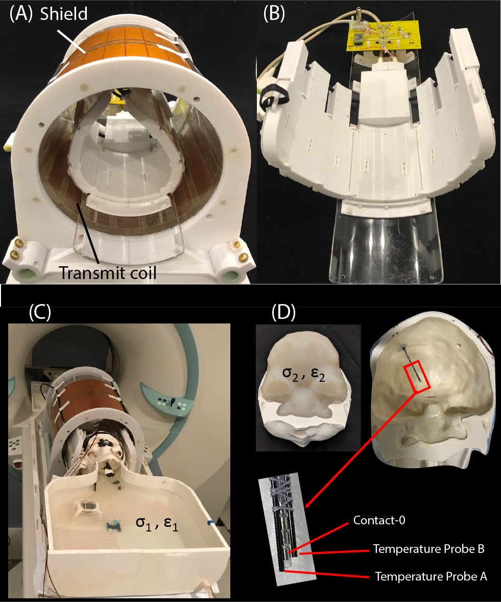
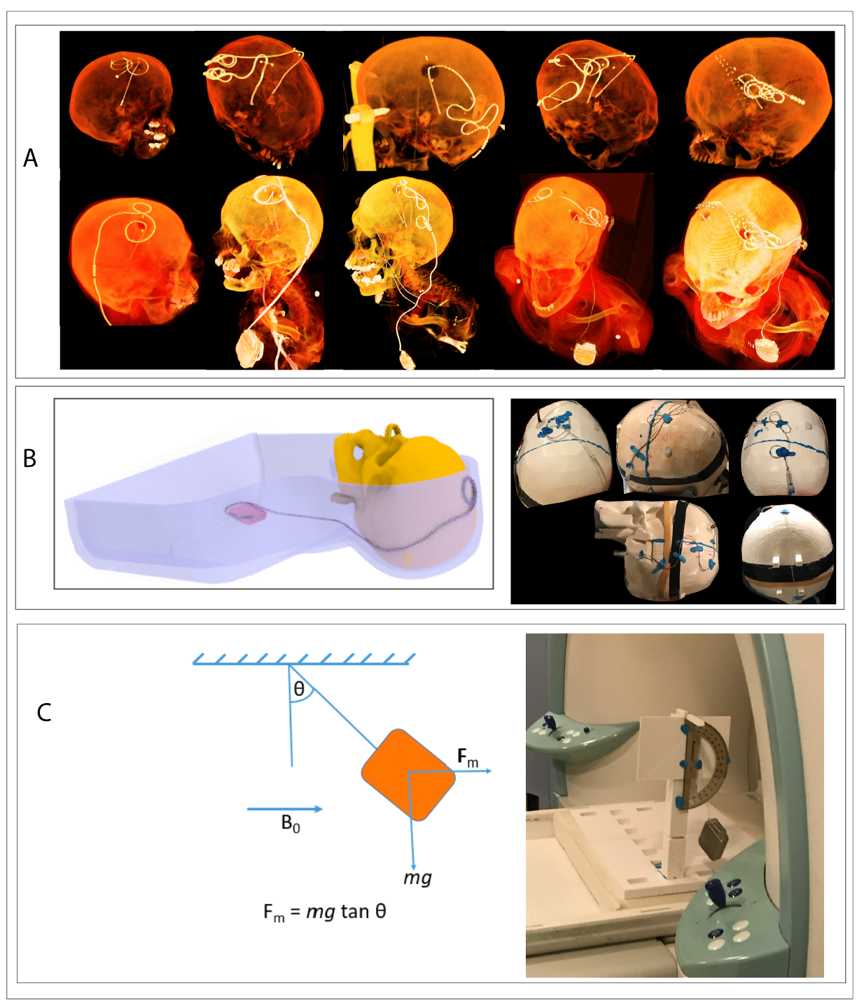
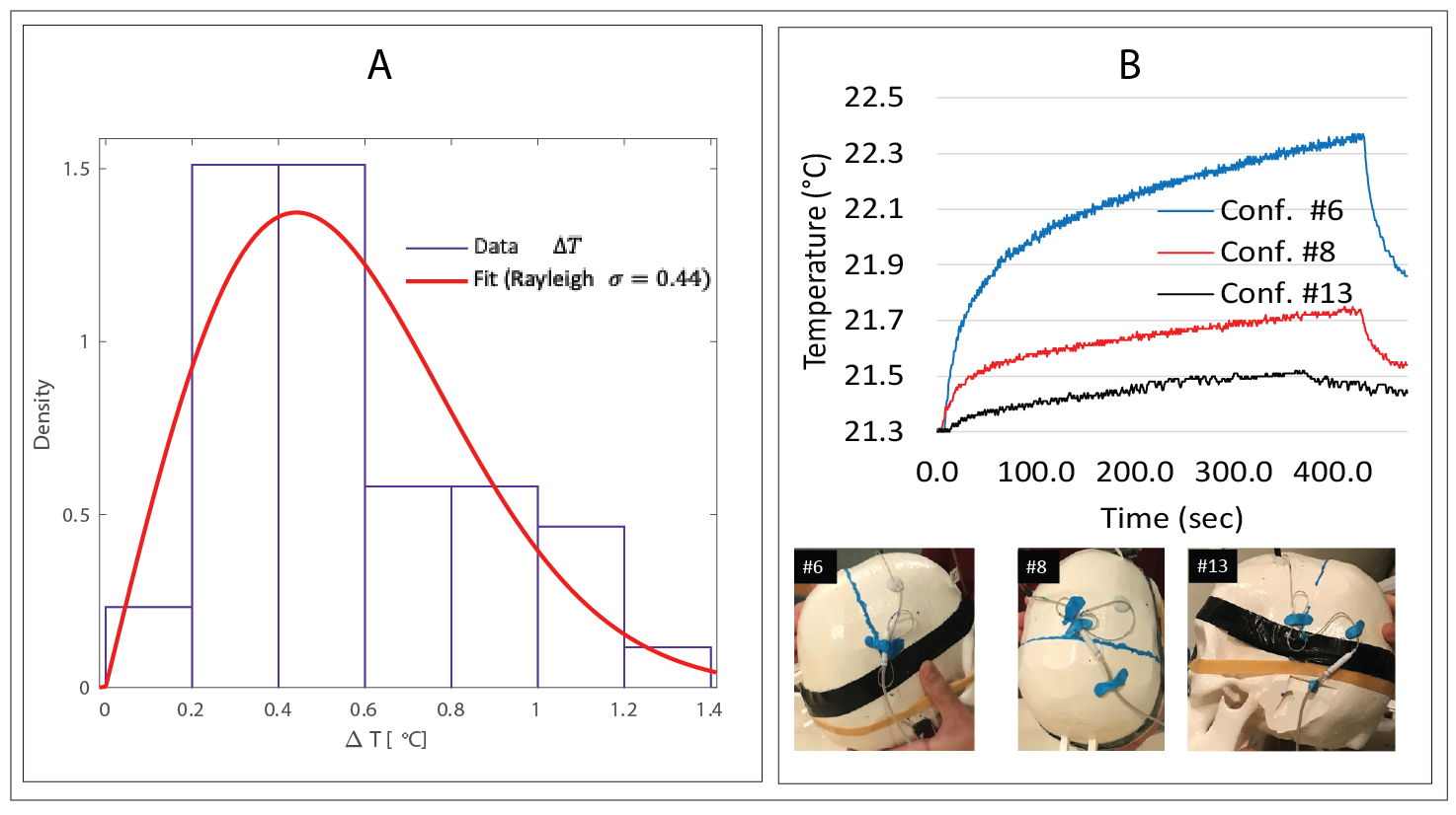
RF exposure: Experiments were performed on a 7T scanner (Magnetom Terra; Siemens Healthineers, Erlangen, Germany) using a home-made local transmit/receive head coil consisting of an 8-channel wrap-around receive array nested inside a shielded detunable quadrature birdcage volume coil (Figure 1 A & B). To allow realistic configuration of DBS devices, we used an anthropomorphic phantom consisting of a 3D-printed body-shaped container and a refillable skull structure designed based on CT images of a DBS patient. The skull was filled with tissue-mimicking gel having electric and thermal properties similar to that of brain tissue (σ = 0.43S/m, thermal conductivity =0.55 J/k-s). Flouroptic temperature sensors were attached to the most distal contact (contact 0) of a Medtronic DBS lead (model 3387 or model 3389) which was inserted into the skull following the position and penetration angle similar to surgical approach for targeting subthalamic nucleus DBS (Figure 1 C & D). We replicated 28 lead-only configurations, where lead trajectories mimicked those observed in postoperative CT images of patients operated at our institutions (Figure 2 A & B). Additionally, we replicated 15 full DBS system configurations, connecting the lead (3389) to an extension (model 3708660) and an implanted pulse generator (IPG) (Activa SC-37603). Finally, we included trajectories that showed maximum heating at lower fields17. RF heating measurements were performed using a high SAR HASTE sequence (TE = 99 msec, TR = 2000 msec, FA = 180°, TA=7:04 minutes).Force measurement: Magnetic force measurement was performed according to the ASTM F2052 test method, using a custom-made device which allowed the IPGs to hang freely using a cotton thread (Figure 2C). The IPG position was varied to find the maximum displacement from the vertical position.
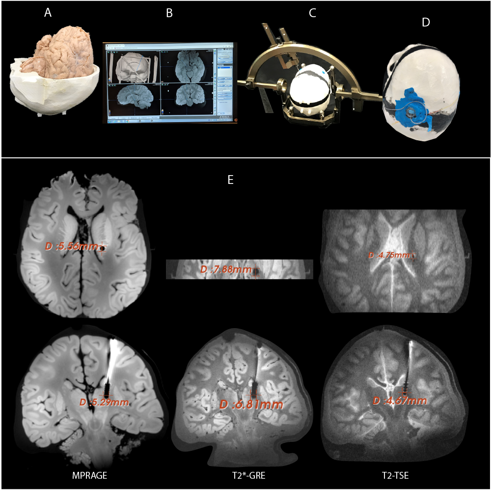
Image artifact: To assess image artifacts, the gel-filled skull was replaced with a skull structure that contained a formalin-fixed human cadaveric brain. A DBS lead (3387) was implanted in the brain following methods similar to DBS implantation targeting right subthalamic nucleus (STN) (Figure 3). Artifacts were assessed on MPRAGE, T2*-GRE and T2-TSE sequences optimized for DBS target visualization14, 15.
Results
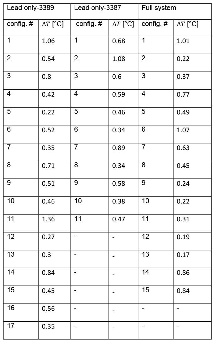
RF heating: The mean ± std of temperature rise ΔT was 0.58 ± 0.23°C for the lead-only system with lead 3387, 0.57 ± 0.30°C for the lead-only system with lead 3389 and 0.52 ± 0.32°C for the full system. A single factor ANOVA showed no significant difference in ΔT between groups (P-value=0.84). The values of temperature increase and related plots are shown in Figure 4 & 5.Magnetic force: The maximum displacement of the IPG from vertical position due to static magnetic force was 25° for IPG Activa PC (37601) and 36° for IPG Activa SC (37603).
Image artifact: The average width of the artifact around the DBS contacts was observed to be 4.7mm, 5.4 mm and 7.3 mm for the sequences T2-TSE, MPRAGE and T2*-GRE respectively.
Discussions
There are strong incentives for the application of ultra-high field MRI in DBS therapy as 1.5T MRI systematically underestimates the boundaries of STN and globus pallidus, the common DBS targets. Furthermore, the contrast to noise ratio is significantly improved at ultra-high field MRI compared to low fields, allowing visualization of DBS small targets. This work represents the first assessment of MRI safety and image artifact during 7T imaging of DBS. The RF induced heating was observed to be less than 2°C for all clinically relevant lead configurations, as well as lead configurations that are shown to generate maximum heating in simulations16. This is less than the temperature increase that occurs during a fever, and indicates RF heating of DBS implants may not be worse than what is observed at lower fields17. Magnetic force measurement showed the force was less than the force due to gravity (angular displacement <45°), implying no hazard would arise due to magnetic force. Artifact measurements indicated that the metal-induced artifacts around leads were comparable to what is observed at lower fields18. The size of artifact, however, was comparable to the size of subthalamic nucleus, therefore making direct target visualization challenging.Conclusions
Our results suggest that 7T MRI may be performed safely in patients with DBS implants for the specific implant models and MRI hardware. However, further studies with different implant models, scanners and transmit coil will be required to generalize this result.Acknowledgements
This work was supported by NIH grant R00EB021320.References
1. Horn A. The impact of modern-day neuroimaging on the field of deep brain stimulation. Current opinion in neurology. 2019;32(4):511-20.
2. Hancu I, Boutet A, Fiveland E, et al. On the (Non‐) equivalency of monopolar and bipolar settings for deep brain stimulation fMRI studies of Parkinson's disease patients. Journal of Magnetic Resonance Imaging. 2019;49(6):1736-49.
3. DiMarzio M, Rashid T, Hancu I, et al. Functional MRI Signature of Chronic Pain Relief From Deep Brain Stimulation in Parkinson Disease Patients. Neurosurgery. 2019;85(6):E1043-E9.
4. Horn A, Wenzel G, Irmen F, et al. Deep brain stimulation induced normalization of the human functional connectome in Parkinson’s disease. Brain. 2019;142(10):3129-43.
5. Baldermann JC, Melzer C, Zapf A, et al. Connectivity profile predictive of effective deep brain stimulation in obsessive-compulsive disorder. Biological psychiatry. 2019;85(9):735-43.
6. Golestanirad L, Keil B, Angelone LM, et al. Feasibility of using linearly polarized rotating birdcage transmitters and close‐fitting receive arrays in MRI to reduce SAR in the vicinity of deep brain simulation implants. Magnetic resonance in medicine. 2017;77(4):1701-12.
7. Golestanirad L, Kazemivalipour E, Keil B, et al. Reconfigurable MRI coil technology can substantially reduce RF heating of deep brain stimulation implants: First in-vitro study of RF heating reduction in bilateral DBS leads at 1.5 T. PloS one. 2019;14(8).
8. Golestanirad L, Iacono MI, Keil B, et al. Construction and modeling of a reconfigurable MRI coil for lowering SAR in patients with deep brain stimulation implants. Neuroimage. 2017;147:577-88.
9. Rezai AR, Phillips M, Baker KB, et al. Neurostimulation system used for deep brain stimulation (DBS): MR safety issues and implications of failing to follow safety recommendations. Investigative radiology. 2004;39(5):300-3.
10. Baker KB, Tkach J, Hall JD, et al. Reduction of magnetic resonance imaging-related heating in deep brain stimulation leads using a lead management device. Neurosurgery. 2005;57(4):392-7.
11. Boutet A, Hancu I, Saha U, et al. 3-Tesla MRI of deep brain stimulation patients: safety assessment of coils and pulse sequences. Journal of Neurosurgery. 2019;132(2):586-94.
12. Plantinga BR, Temel Y, Duchin Y, et al. Individualized parcellation of the subthalamic nucleus in patients with Parkinson's disease with 7T MRI. Neuroimage. 2018;168:403-11.
13. Maruyama S, Fukunaga M, Fautz H-P, et al. Comparison of 3T and 7T MRI for the visualization of globus pallidus sub-segments. Scientific Reports. 2019;9(1):1-8.
14. Alkemade A, de Hollander G, Keuken MC, et al. Comparison of T2*-weighted and QSM contrasts in Parkinson's disease to visualize the STN with MRI. PloS one. 2017;12(4):e0176130.
15. Abosch A, Yacoub E, Ugurbil K, Harel NJN. An assessment of current brain targets for deep brain stimulation surgery with susceptibility-weighted imaging at 7 tesla. 2010;67(6):1745-56.
16. Golestanirad L, Kirsch J, Bonmassar G, et al. RF-induced heating in tissue near bilateral DBS implants during MRI at 1.5 T and 3T: The role of surgical lead management. NeuroImage. 2019;184:566-76.
17. Bhusal B, Nguyen BT, Sanpitak PP, et al. Effect of Device Configuration and Patient's Body Composition on the RF Heating and Nonsusceptibility Artifact of Deep Brain Stimulation Implants During MRI at 1.5 T and 3T. J Magn Reson Imaging. 2020.
18. Boutet A, Rashid T, Hancu I, et al. Functional MRI safety and artifacts during deep brain stimulation: experience in 102 patients. Radiology. 2019;293(1):174-83.
Figures