0415
Open-bore vertical MRI scanners generate significantly lower RF heating around DBS implants: A Simulation study with experimental validation1Northwestern University, Chicago, IL, United States, 2Bilkent University, Ankara, Turkey, 3Massachusetts General Hospital, Charlestown, MA, United States, 4Illinois Bone and Joint Institute, Wilmette, IL, United States, 5Albany Medical College, Albany, NY, United States
Synopsis
Though there are many studies reporting RF heating of implants in horizontal MRI scanners, there is almost no literature on vertical scanners that have 90° rotated transmit coils and a fundamentally different distribution of RF fields. Here we evaluate RF heating of deep brain stimulation (DBS) implants during MRI in a 1.2T open-bore vertical scanner compared to a 1.5T horizontal system with both numerical simulations and experimental measurements. We found a significant reduction in RF heating using vertical vs horizontal RF coils which are attributable to the orthogonal orientation of RF electric fields.
Introduction
RF heating of tissue around conductive implants is a major issue, restricting access to MRI for thousands of patients annually1-5. To date, majority of studies on RF heating of implants have been performed on horizontal close-bore (solenoidal) MRI scanners6-10. Vertical MRI systems, originally introduced as open low-field scanners, are now available at 1.2T, capable of high-resolution structural and functional imaging. As these scanners have a 90° rotated B1+, they generate a fundamentally different RF field distribution, and by proxy RF heating, compared to horizontal scanners. Almost no implant SAR literature exists for this class of scanners, except a recent simulation study in 3 patients with deep brain stimulation (DBS) implants which showed a substantial SAR reduction in vertical vs horizontal MRI systems11. Here we report results of the first large-scale simulation study of SAR in 90 patient-derived DBS lead models during MRI in a 1.2 T OASIS Hitachi scanner compared to a 1.5T horizontal system. Simulation results were validated in experiments with a commercial DBS device implanted in an anthropomorphic phantom. We found a significant reduction in SAR (30-fold, P˂1×10⁻⁵) and RF heating (10-fold, P ˂ 0.025) of implanted leads during RF exposure with Hitachi 1.2T OASIS coil compared to Siemens 1.5T Aera coil.Methods
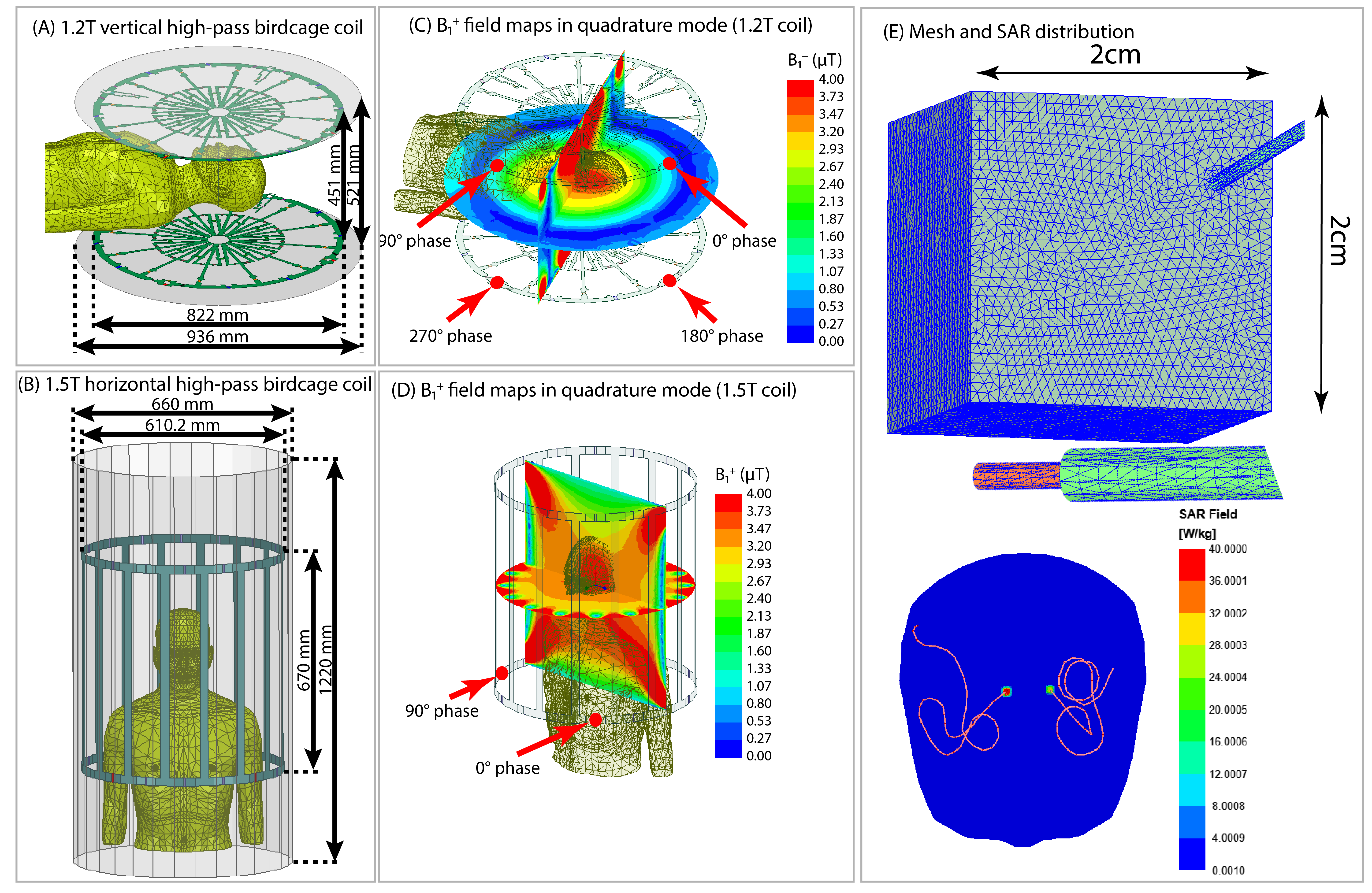
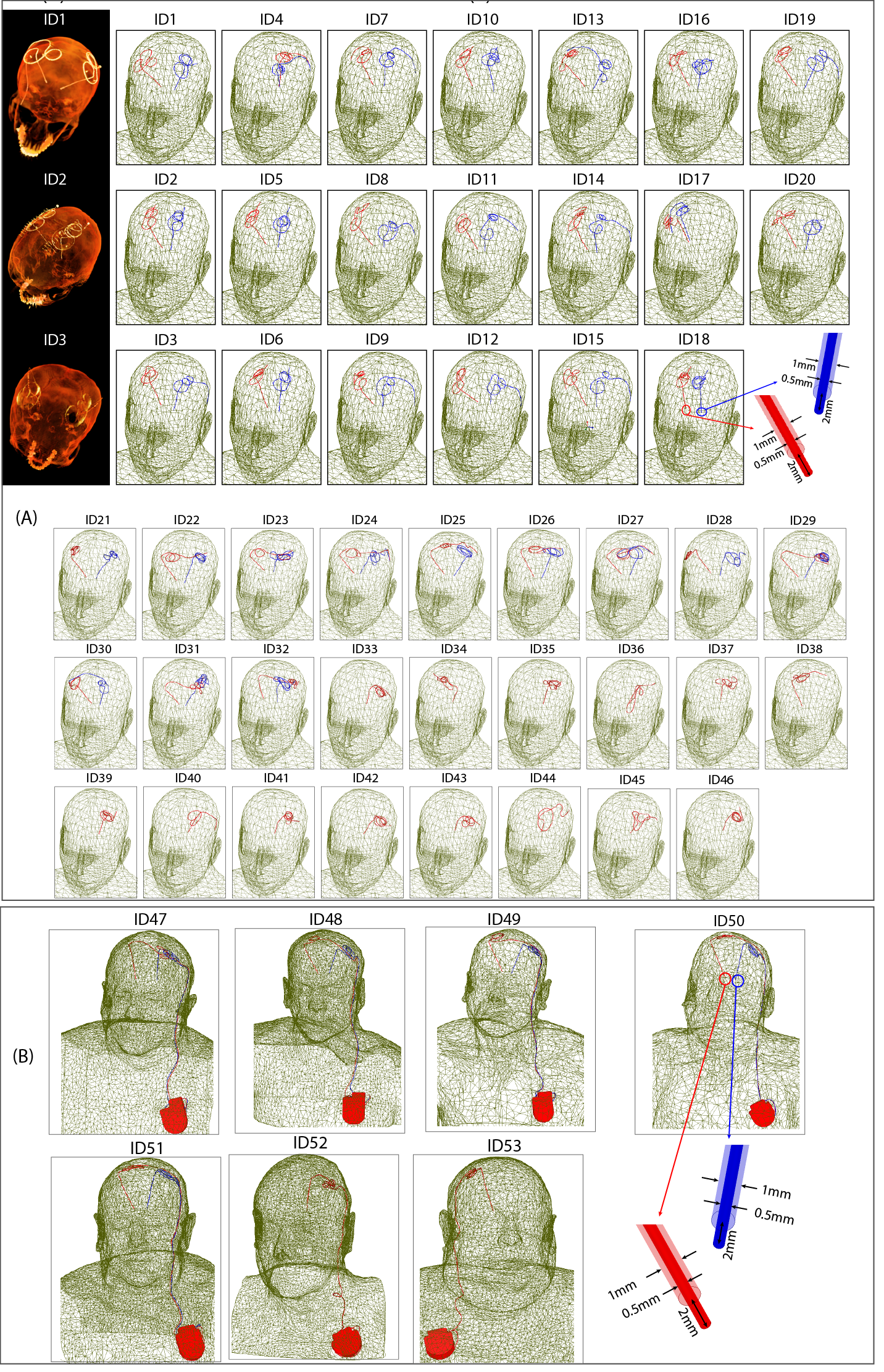
We constructed numerical models of a high-pass radial planar birdcage coil made of 12 vertical rungs tuned to 50.4 MHz (1.2T proton imaging) and a 16-rung high-pass birdcage coil tuned to 64 MHz (1.5T proton imaging). The coil configurations and respective field distributions are shown in Figure 1 (A-D). The vertical coil geometry and circuitry was based on information provided by the vendor. The horizontal coil was modelled using dimensions similar to those reported in the literature12. To distinguish the effects of resonance frequency from field orientation, we also simulated the SAR generated by a horizontal birdcage coil with the same physical dimensions as the 1.5 T birdcage coil but tuned to 50.4 MHz for comparison.Ninety (90) unique lead models were simulated with realistic trajectories extracted from postoperative computed tomography (CT) images of 53 patients with both lead-only and fully implanted DBS systems (Figure 2). To account for variation in lead trajectories, patients were recruited from two DBS centers operated by different neurosurgeons (JR and JP). Simulations were performed at head imaging landmark representing MRI for DBS target visualization.
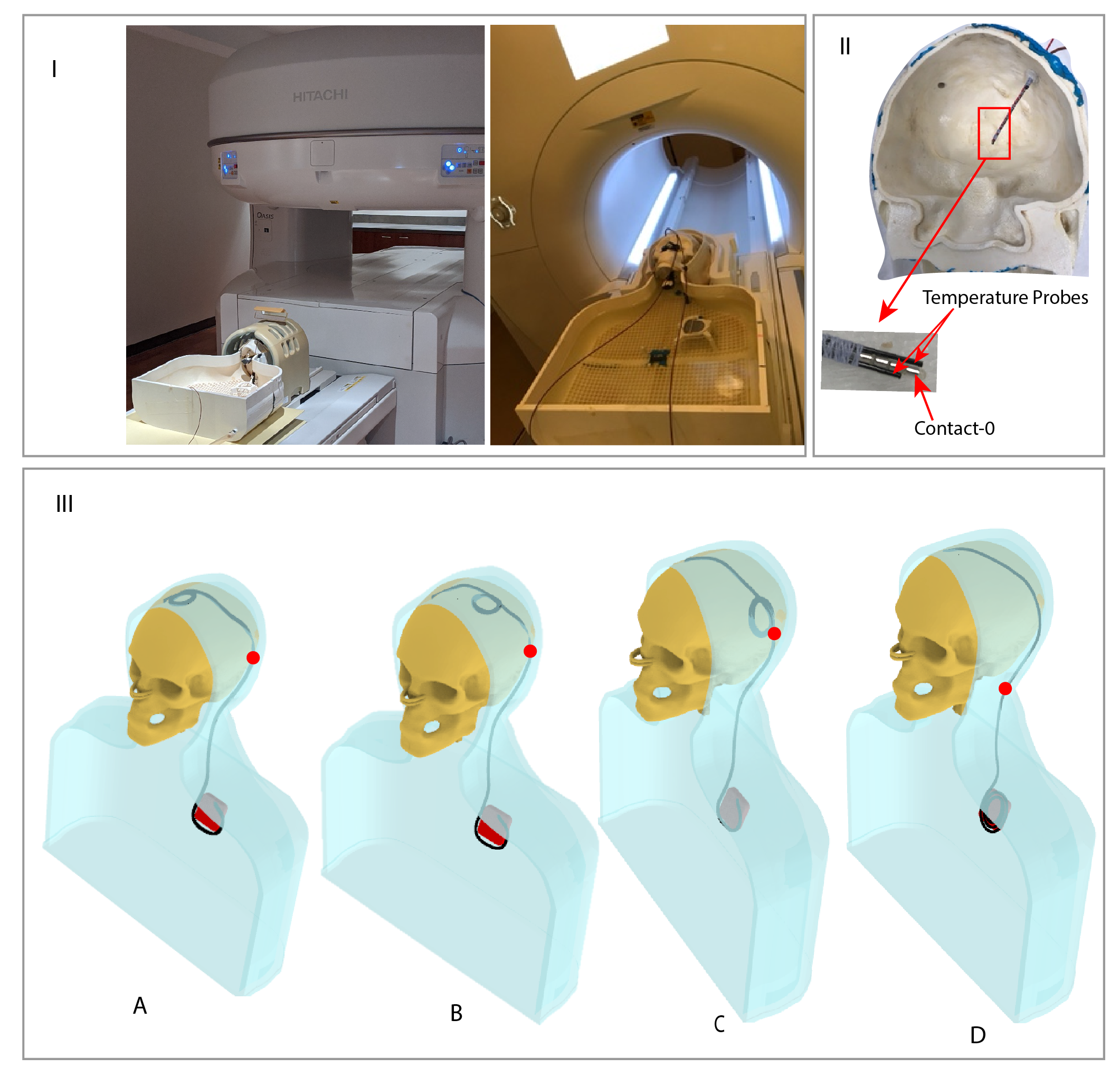
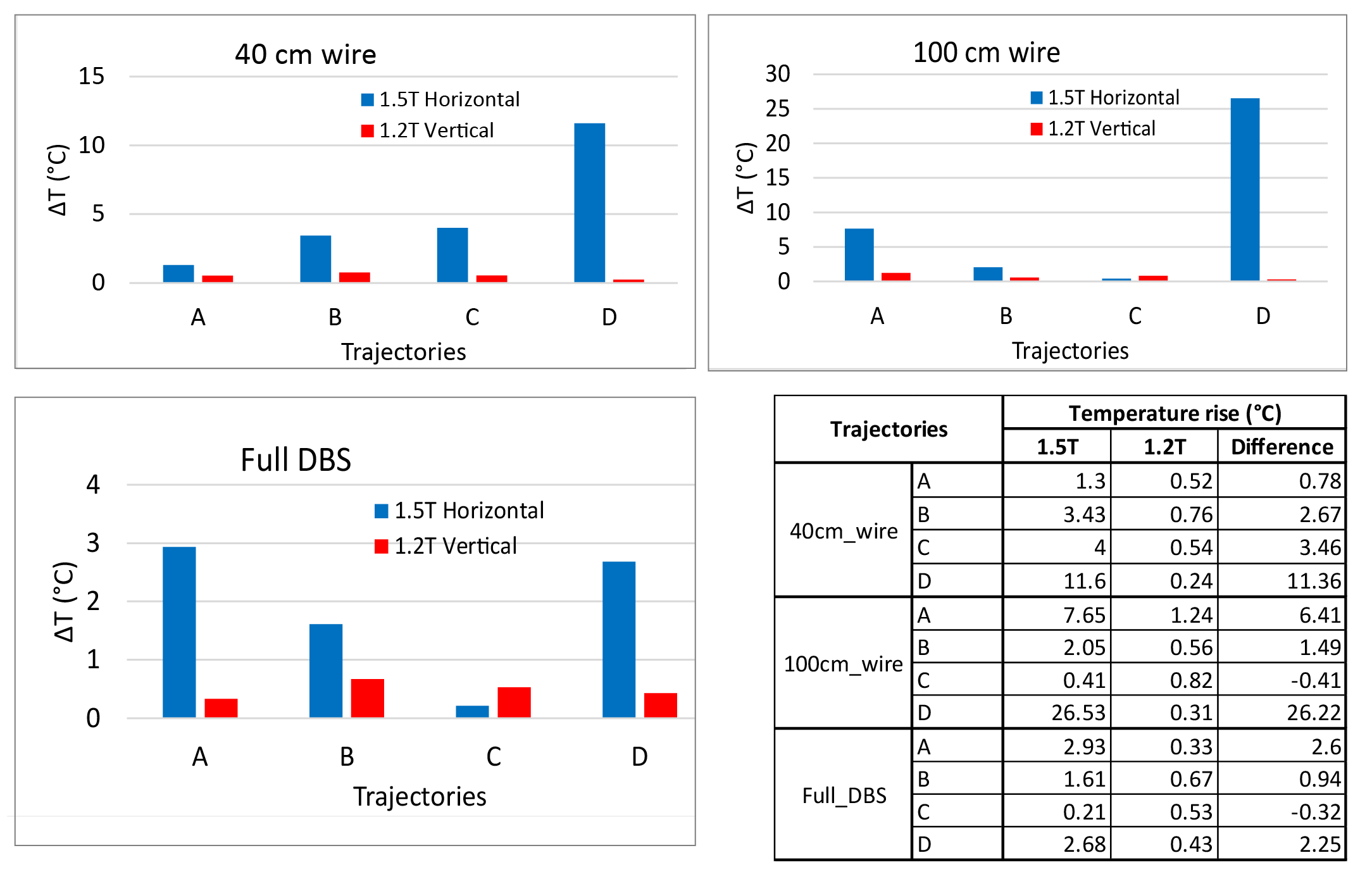
Experiments were performed in a 1.2T vertical scanner (Hitachi 1.2T OASIS) and a 1.5T horizontal scanner (Siemens 1.5T Aera) using an anthropomorphic phantom which consisted of a human body shaped torso and a 3D printed skull (Figure 3 (I)). The skull was filled with a tissue-mimicking gel with electric and thermal properties similar to brain gray matter (σ =0.40 S/m and thermal conductivity 0.55 J/k-s) and the body was filled with saline (σ =0.48 S/m). The phantom was implanted with 40 cm wires representing lead-only DBS systems and 100 cm wires representing full DBS system, as well as a commercial DBS device (Medtronic Inc., Minneapolis, MN). Temperature increase during MRI was measured using flouroptic temperature probes attached to the lead tip (Figure 3 (II). For each lead/wire model, four different trajectories were implemented as shown in Figure 3 (III). Trajectory A consisted of two concentric loops at the surgical burr hole, Trajectory B consisted of two concentric loops moved farther from burr hole along the coronal suture and Trajectory C consisted of two loops above the temporal bone. Trajectory D has no loop on the skull. Trajectory A and C are shown to minimize RF heating of fully implanted DBS device at 3T and 1.5T respectively whereas Trajectory D is shown to produce higher heating at both 1.5T and 3T horizontal scanners10. A high SAR turbo spin echo (TSE) sequence was used, with parameters adjusted to produce rms B1+ of 4 µT at both scanners.
Results
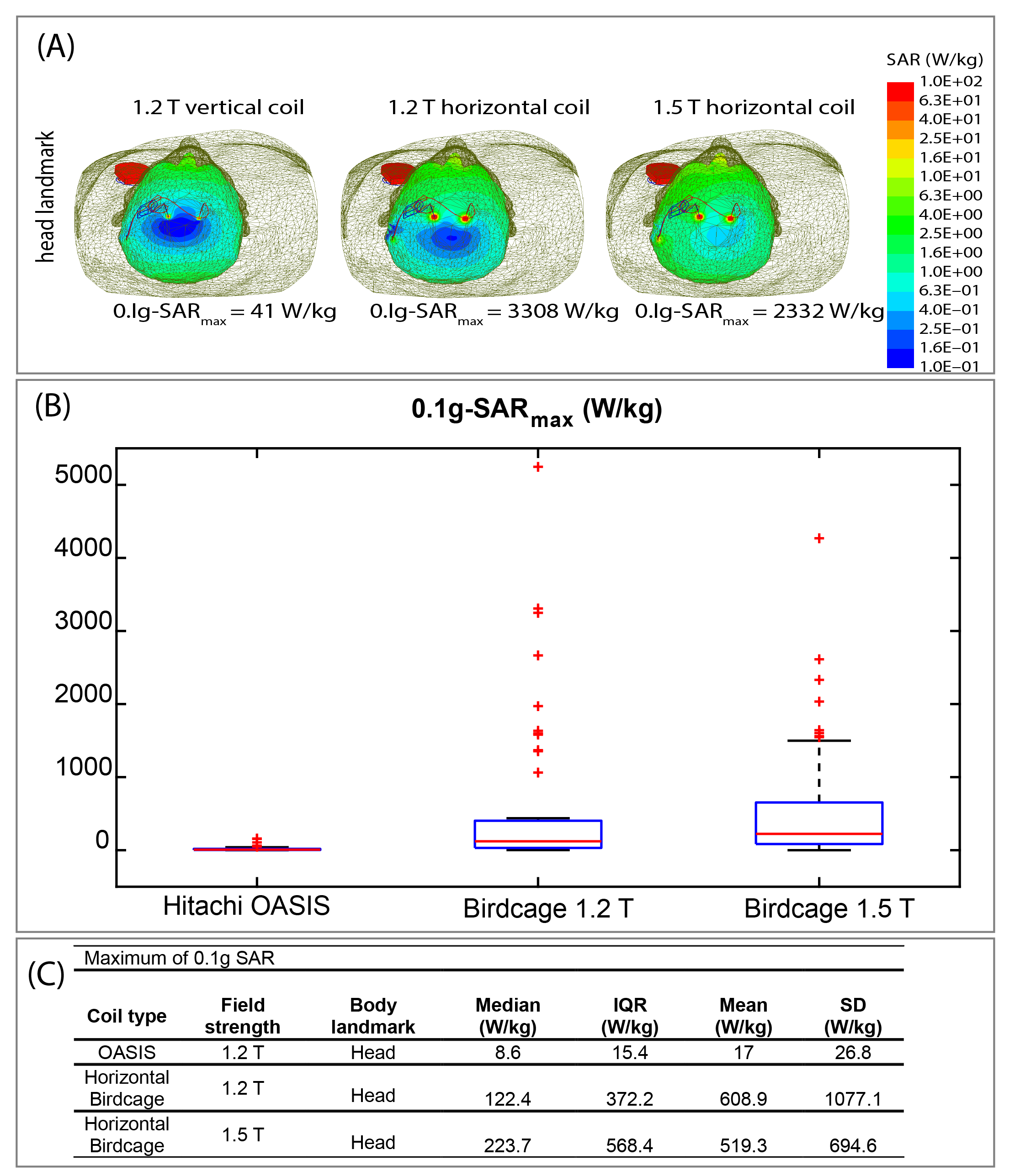
The mean ± standard deviation of maximum value of 0.1g averaged SAR (0.1g-SARmax) was 17±26.8 W/kg for the 1.2T OASIS coil, 519.3±694.6 W/kg for the 1.5 T horizontal birdcage coil, and 608.9±1077.1 W/kg for 1.2T horizontal birdcage coil. This indicates ~30-fold reduction in mean value of 0.1g-SARmax in 1.2T vertical coil compared to 1.5T and 1.2T horizontal coils. A paired one-tailed t-test showed significant reduction in 0.1g-SAR using 1.2T OASIS vertical coil compared to 1.5 T horizontal birdcage coil (P˂1×10⁻⁵, Cohen’s d =0.73) as well as 1.2T horizontal birdcage coil (P˂1.7×10⁻⁴, Cohen’s d =0.55).The mean± standard deviation of ΔT was 5.36±7.40 ºC in the 1.5T horizontal scanner and 0.58±0.27 ºC in the 1.2T vertical scanner, indicating a 10-fold reduction in mean temperature rise using vertical scanner. Additionally, the worst-case heating at 1.5T horizontal scanner was 21-fold higher than the worst-case heating at 1.2T vertical scanner (26.53ºC vs 1.24ºC). A one tailed paired t-test showed a significant reduction in heating at 1.2T vertical scanner compared to 1.5T horizontal scanner (p ˂ 0.025, Cohen’s d =0.64).
Discussions and Conclusions
Our work provides strong evidence of a significantly reduced RF heating around implanted conductive leads generated by vertical transmit coils compared to conventional birdcage coils. If verified with other types of implants, this indicates new possibilities for scanning of patients with electronically active implants.Acknowledgements
This work was supported by the NIH grants R00EB021320 and R03EB025344.References
1. Rezai AR, Phillips M, Baker KB, et al. Neurostimulation system used for deep brain stimulation (DBS): MR safety issues and implications of failing to follow safety recommendations. Investigative radiology. 2004;39(5):300-3.
2. Bhusal B, Bhattacharyya P, Baig T, et al. Measurements and simulation of RF heating of implanted stereo‐electroencephalography electrodes during MR scans. 2018;80(4):1676-85.
3. Vu J, Bhusal B, Nguyen BT, Golestanirad L. Evaluating Accuracy of Numerical Simulations in Predicting Heating of Wire Implants During MRI at 1.5 T. 2020 42nd Annual International Conference of the IEEE Engineering in Medicine & Biology Society (EMBC), 2020. IEEE: 6107-10.
4. Golestanirad L, Kirsch J, Bonmassar G, et al. RF-induced heating in tissue near bilateral DBS implants during MRI at 1.5 T and 3T: The role of surgical lead management. NeuroImage. 2019;184:566-76.
5. Golestanirad L, Angelone LM, Kirsch J, et al. Reducing RF-induced heating near implanted leads through high-dielectric capacitive bleeding of current (CBLOC). IEEE transactions on microwave theory and techniques. 2019;67(3):1265-73.
6. McElcheran CE, Yang B, Anderson KJ, et al. Parallel radiofrequency transmission at 3 tesla to improve safety in bilateral implanted wires in a heterogeneous model. Magnetic resonance in medicine. 2017;78(6):2406-15.
7. Nguyen BT, Pilitsis J, Golestanirad L. The effect of simulation strategies on prediction of power deposition in the tissue around electronic implants during magnetic resonance imaging. Journal of Physics in Medicine and Biology. 2020;65(18):185007.
8. Kazemivalipour E, Keil B, Vali A, et al. Reconfigurable MRI technology for low-SAR imaging of deep brain stimulation at 3T: Application in bilateral leads, fully-implanted systems, and surgically modified lead trajectories. NeuroImage. 2019;199:18-29.
9. Oh S, Webb AG, Neuberger T, et al. Experimental and numerical assessment of MRI‐induced temperature change and SAR distributions in phantoms and in vivo. 2010;63(1):218-23.
10. Bhusal B, Nguyen BT, Sanpitak PP, et al. Effect of Device Configuration and Patient's Body Composition on the RF Heating and Nonsusceptibility Artifact of Deep Brain Stimulation Implants During MRI at 1.5 T and 3T. Journal of Magnetic Resonance Imaging 2020;(In Press).
11. Golestanirad L, Kazemivalipour E, Lampman D, et al. RF heating of deep brain stimulation implants in open‐bore vertical MRI systems: A simulation study with realistic device configurations. Magnetic Resonance in Medicine. 2020;83(6):2284-92.
12. Yeo DT, Wang Z, Loew W, et al. Local SAR in high pass birdcage and TEM body coils for multiple human body models in clinical landmark positions at 3T. Journal of magnetic resonance imaging: JMRI. 2011;33(5):1209.
Figures