0414
Implant-Friendly Excitation Strategies for Imaging DBS Electrodes at 7T
Alireza Sadeghi-Tarakameh1, Lance DelaBarre1, Nur Izzati Huda Zulkarnain1, Noam Harel1, and Yigitcan Eryaman1
1Center for Magnetic Resonance Research (CMRR), University of Minnesota, Minneapolis, MN, United States
1Center for Magnetic Resonance Research (CMRR), University of Minnesota, Minneapolis, MN, United States
Synopsis
We mitigated the radiofrequency heating at the contacts of a DBS electrode by utilizing an implant-friendly (IF) excitation scenario at 7T. IF modes of a 16-channel transmit/receive coil are calculated by minimizing electrode-shaft current close to the contacts. An IF excitation is calculated by shimming the B1+ field in an ROI using individual IF modes of the array. The proposed approach is able to mitigate the shaft current and RF heating at the contacts.
Introduction
Radiofrequency (RF) heating of the deep brain stimulation (DBS) electrodes is a patient safety problem in MRI.1 In addition to many other factors, heating strictly depends on the trajectory of the electrode.2-4 Therefore, patient-specific solutions are needed to tackle this problem. Previously, it was shown that an optimized dual-drive excitation could significantly reduce the induced current and RF heating at the tip of the electrode at 1.5T and 3T.5-9 In addition, transmit array (TxArray) technology has been proved to be effective for mitigating induced currents9-12 as well as improving excitation inhomogeneity in the presence of metallic devices.13-15Despite the extensive investigation at 1.5 T and 3T, TxArrays’ potential for minimizing implant heating is not investigated in detail at ultra-high-fields (UHF, B0 ≥ 7T). In this work, motivated by the success of previously proposed strategies7-12, we investigated implant-friendly excitation solutions at 7T. For that purpose, we mitigated the RF heating at the contacts of an electrode by minimizing the shaft current near the contacts of an electrode. We calculated implant-friendly (IF) modes of a 16-channel TxArray coil and performed RF shimming. We experimentally measured the temperature increase at the contacts and calculated the standard deviation of the image intensity at the vicinity of the electrode.
Theory and Method
All experiments are conducted at a 7T scanner (Magnetom 7T, Siemens Healthineers, Erlangen, Germany) and using a commercial DBS electrode (directional lead for the Infinity DBS system, Abbott Laboratories, Chicago, IL) immersed into a human head-shaped uniform phantom (Fig. 2). A 16-channel transmit/receive transmission line array is used during the experiments.16Fig. 1 show the steps we propose for calculating the implant-friendly modes. First, we ran a fast/low-power B1-mapping sequence. We obtained relative complex B1+ maps of individual channels at two planes, P1 and P2. (see figure 2). Location of P1 and P2 are chosen such that, P2 contained the incident B1+ field, whereas P1 contained the superposition of the incident and the scattered B1+ field around the electrode.
Assuming that the incident B1+ field close to the electrode at P1 and P2 are approximately equal, field maps at these two planes are subtracted from each other. This allowed us to approximate the scattered field from the electrode due to the excitation of individual channels. To find the relative shaft current induced by ith channel (i >1) we searched for an optimal channel weight wi, which minimizes the difference between the 1st and ith coils’ scattered fields. The shaft current induced by the ith coil is then calculated by Ii= 1/wi. We repeated this procedure for all channels and calculated 15 relative complex shaft currents (the shaft current induced by channel 1 was assumed to have a unit value). Finally, we computed the null space of the row vector containing all shaft currents and obtained 15 IF modes.
To validate the IF excitation conditions, we exposed the experimental set-up to RF energy with the IF modes using a hard RF pulse (average incident power of 6W). We monitored the temperature progression at the tip of the electrode using a fiber optic temperature probe (Lumasense Technologies, CA). In addition, we measured the heating due to four additional excitation patterns as well as the worst-case heating scenario (maximum shaft current) due to 6W of incident power. Finally, we shimmed the B1+ in a 2D-rectangular ROI using:
1) Scanner’s shimming toolbox (all channels included)
2) IF modes only
Turbo spin-echo (TSE) images (FA=180°, TR=3020ms, Echo train length=11) were acquired using both shimming solutions. The standard deviation (SD) of the image intensity around the electrode is calculated, and the temperature increase is reported for both scenarios.
Results
Fig. 3 shows the B1+-maps corresponding to each channel as well as each IF mode. Fig. 4a-c show the time-progression of the temperature at the tip of the electrode corresponding to each IF mode, four random excitations, and the worst-case heating scenario, respectively. We observed no temperature increase when IF modes are used. Four additional patterns caused significant temperature increase at the contacts, whereas the worst-case excitation resulted in the largest temperature increase as expected.Fig. 5 shows the TSE images acquired using the shim solutions for the ROI achieved by the scanner’s shimming toolbox and IF strategy, respectively. The IF excitation did not cause any measurable temperature increase at the contacts, whereas the scanner’s shimming method caused a temperature increase of ~2.6°C.
Discussion
The IF excitation strategy is demonstrated with a DBS electrode placed inside a uniform phantom. The strategy should be investigated for various realistic electrode trajectories as well as non-uniform media.For the scattered field approximation, the incident B1+ at planes P1 and P2 is assumed to be approximately equal. Although this assumption was justified in this experimental set-up, it needs to be investigated further for non-homogeneous medium as well. Detailed EM simulations as well as cadaver studies may be useful for that purpose.
Conclusion
We demonstrated that implant friendly excitation strategies could be employed to mitigate RF-induced currents and RF heating while imaging DBS electrodes at 7T. With the recent FDA approval of 7T systems for clinical use, these strategies will be even more applicable.Acknowledgements
This work was supported by the following grant: NIBIB P41 EB027061, NINDS R01NS115180, and devices were donated by Abbott Neuromodulation.References
- Henderson JM, Tkach J, Phillips M, Baker K, Shellock FG, Rezai AR. Permanent neurological deficit related to magnetic resonance imaging in a patient with implanted deep brain stimulation electrodes for Parkinson’s disease: case report. Neurosurgery 2005;57(5):E1063; discussion E63 doi: 10.1227/01.neu.0000180810.16964.3e[published Online First: Epub Date]|.
- Yeung CJ, Susil RC, Atalar E. RF safety of wires in interventional MRI: using a safety index. Magnetic Resonance in Medicine: An Official Journal of the International Society for Magnetic Resonance in Medicine. 2002 Jan;47(1):187-93.
- Guerin B, Iacono MI, Davids M, Dougherty D, Angelone LM, Wald LL. The ‘virtual DBS population’: five realistic computational models of deep brain stimulation patients for electromagnetic MR safety studies. Phys Med Biol 2019;64(3):035021 doi: 10.1088/1361-6560/aafce8[published Online First: Epub Date]|.
- Guerin B, Serano P, Iacono MI, et al. Realistic modeling of deep brain stimulation implants for electromagnetic MRI safety studies. Phys Med Biol 2018;63(9):095015 doi: 10.1088/1361-6560/aabd50[published Online First: Epub Date]|.
- Golestanirad L, Angelone LM, Iacono MI, Katnani H, Wald LL, Bonmassar G. Local SAR near deep brain stimulation (DBS) electrodes at 64 and 127 MHz: A simulation study of the effect of extracranial loops. Magn Reson Med 2017;78(4):1558-65 doi: 10.1002/mrm.26535[published Online First: Epub Date]|.
- Eryaman Y, Akin B, Atalar E. Reduction of implant RF heating through modification of transmit coil electric field. Magnetic resonance in medicine. 2011 May;65(5):1305-13.
- Eryaman Y, Turk EA, Oto C, Algin O, Atalar E. Reduction of the radiofrequency heating of metallic devices using a dual‐drive birdcage coil. Magnetic resonance in medicine. 2013 Mar 1;69(3):845-52.
- Kazemivalipour E, Keil B, Vali A, Rajan S, Elahi B, Atalar E, Wald LL, Rosenow J, Pilitsis J, Golestanirad L. Reconfigurable MRI technology for low-SAR imaging of deep brain stimulation at 3T: Application in bilateral leads, fully-implanted systems, and surgically modified lead trajectories. NeuroImage. 2019 Oct 1;199:18-29.
- Golestanirad L, Kazemivalipour E, Keil B, Downs S, Kirsch J, Elahi B, Pilitsis J, Wald LL. Reconfigurable MRI coil technology can substantially reduce RF heating of deep brain stimulation implants: First in-vitro study of RF heating reduction in bilateral DBS leads at 1.5 T. PloS one. 2019 Aug 7;14(8):e0220043.
- Eryaman Y, Guerin B, Akgun C, Herraiz JL, Martin A, Torrado‐Carvajal A, Malpica N, Hernandez‐Tamames JA, Schiavi E, Adalsteinsson E, Wald LL. Parallel transmit pulse design for patients with deep brain stimulation implants. Magnetic resonance in medicine. 2015 May;73(5):1896-903.
- McElcheran CE, Yang B, Anderson KJ, Golenstani-Rad L, Graham SJ. Investigation of parallel radiofrequency transmission for the reduction of heating in long conductive leads in 3 Tesla magnetic resonance imaging. PLoS One. 2015 Aug 3;10(8):e0134379.
- Etezadi‐Amoli M, Stang P, Kerr A, Pauly J, Scott G. Controlling radiofrequency‐induced currents in guidewires using parallel transmit. Magnetic resonance in medicine. 2015 Dec;74(6):1790-802.
- Zhu Y. Parallel excitation with an array of transmit coils. Magnetic Resonance in Medicine: An Official Journal of the International Society for Magnetic Resonance in Medicine. 2004 Apr;51(4):775-84.
- Metzger GJ, Snyder C, Akgun C, Vaughan T, Ugurbil K, Van de Moortele PF. Local B1+ shimming for prostate imaging with transceiver arrays at 7T based on subject‐dependent transmit phase measurements. Magnetic Resonance in Medicine: An Official Journal of the International Society for Magnetic Resonance in Medicine. 2008 Feb;59(2):396-409.
- Adriany G, Auerbach EJ, Snyder CJ, Gözübüyük A, Moeller S, Ritter J, Van de Moortele PF, Vaughan T, Uğurbil K. A 32‐channel lattice transmission line array for parallel transmit and receive MRI at 7 tesla. Magnetic Resonance in Medicine: An Official Journal of the International Society for Magnetic Resonance in Medicine. 2010 Jun;63(6):1478-85.
- Adriany G, Van de Moortele PF, Ritter J, Moeller S, Auerbach EJ, Akgün C, Snyder CJ, Vaughan T, Uğurbil K. A geometrically adjustable 16‐channel transmit/receive transmission line array for improved RF efficiency and parallel imaging performance at 7 Tesla. Magnetic Resonance in Medicine: An Official Journal of the International Society for Magnetic Resonance in Medicine. 2008 Mar;59(3):590-7.
Figures
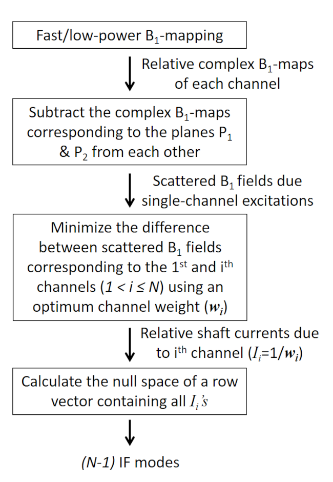
Figure 1. Summary of the proposed method to obtain the
implant-friendly modes of a TxArray coil.
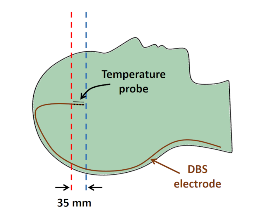
Figure 2. A drawing of the experimental set-up
demonstrating positions of the electrode, temperature probe, and the planes
used for B1 mapping. A commercial DBS electrode and an optic
temperature probe were immersed into a human head-shaped uniform gel phantom.
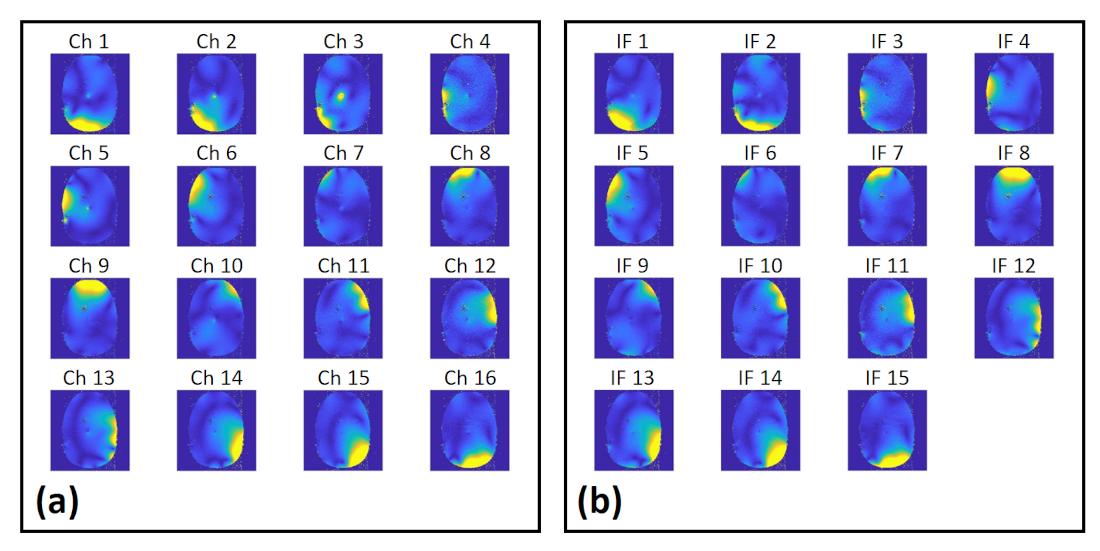
Figure
3. B1-maps corresponding to (a) individual
channels and (b) each implant-friendly mode.
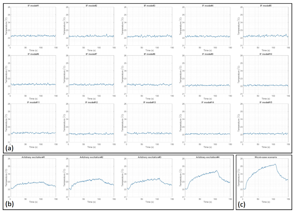
Figure 4. Temperature measurements at the tip of the DBS
electrode exposed to a 6W hard RF pulse using (a) implant-friendly modes, (b)
random excitations, and (c) the worst-case scenario.
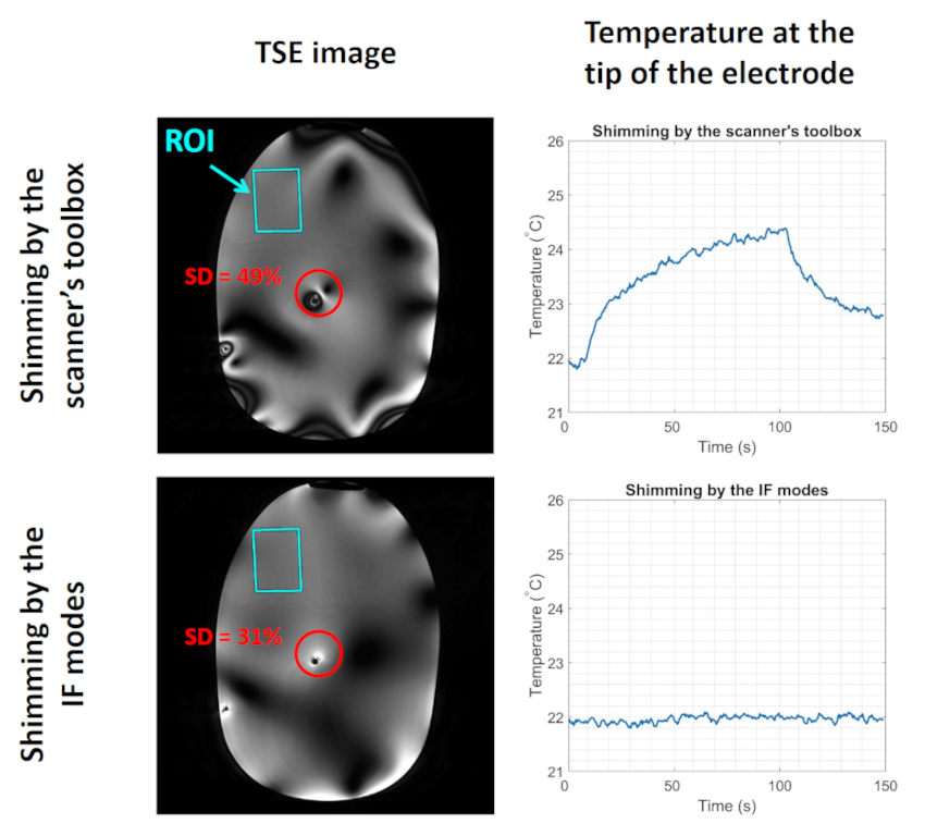
Figure 5. RF shimming
inside the indicated ROI using the scanner’s shimming toolbox vs. the IF modes.
Turbo spin-echo images were acquired, and the electrode’s tip temperatures were
measured for both shimming scenarios.