0364
MR Safety Assessments of Active Implantable and Interventional Devices in a Single Measurement Setup1Deptartment of Radiology, Medical Physics, University Medical Center Freiburg, University of Freiburg, Freiburg, Germany, 2German Consortium for Translational Cancer Research Partner Site Freiburg, German Cancer Research Center (DKFZ), Heidelberg, Germany, 3Institute of Biomedical Engineering, Bogazici University, Istanbul, Turkey, 4Cardiovascular Branch, Division of Intramural Research, National Heart Lung and Blood Institute, National Institutes of Health, Bethesda, MD, United States, 5Transmural Systems, Andover, MA, United States
Synopsis
Interventional devices such as actively visualized catheters or guidewires have a long conductive line between the source and the probe at the tip. Long conductive wires can interract with the electromagnetic fields generated by the transmit coils resulting in RF-induced heating of surrounding tissue. Existing standards do not cover partial immersion and dynamic motion of such devices. In this study, we propose an automated electric field detection and mapping system that is capable of performing hotspot detection, transfer function(TF) measurement and TF validation using different dipole antennae. RF-induced heating can be evaluated without moving the device, thus eliminating positioning errors.
Introduction
RF-induced heating of implants and devices in the MRI environment is a result of the coupling of external electromagnetic (EM) transmit fields with elongated metallic structures [1], [2]. To assess this coupling, Park et al. [3] describe a domain decomposition approach (Tier 3 Clause #8, ISO/TS 10974 Ed2) which analyses the RF exposure by the MRI RF transmit coil using a set of clinically relevant incident tangential RF electric fields (Etan(z)) along the lead pathways in combination with a position-independent lead RF response, the so-called transfer function (TF). Although the ISO standard is intended for AIMDs, in principle it can also be applied to actively-visualized interventional catheters and guidewires (AICs and AIGWs). The additional challenges of AICs and AIGWs that are not covered by the ISO/TS 10974 Ed2 are that AICs and AIGWs are partially immersed in the body, that their insertion length is not constant over time, and that the temperature hot spot is not necessarily an exposed tip. Previously we showed that insertion length is a significant parameter in RF-induced heating of AICs [4], [5]. Recently, we also introduced a novel TF measurement that can perform measurements of partially immersed leads [6]. Using these concepts, in this study TF measurements are performed in an AIGW for 23.66MHz 64MHz, and 123MHz using a single setup based on a metal-free broadband electric field sensor. We also propose a new method for TF validation, where dipole antennae with different patterns are used to generate uncorrelated Etan(z).Methods
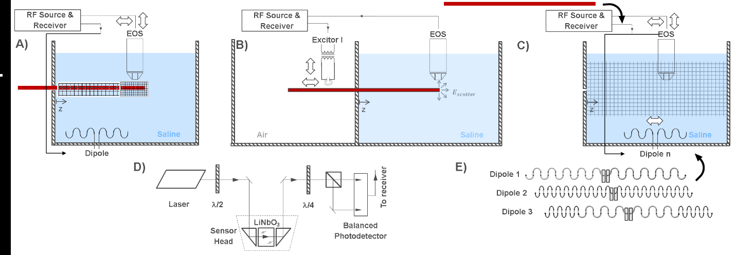
A schematic of the setup for hotspot detection, TF measurement, and TF-validation modes of the setup is shown in Fig. 1. A main element of the setup is an electro-optic E-field sensor (EOS) with a detection bandwidth that is only limited by the sampling rate of the receiver (UHFLI, Zurich Instruments, Switzerland), 1.8 GSamples/s [7], [8]. E- and B- fields are generated by a dipole antenna and/or a local excitor which are tuned to the resonance frequency and matched to 50W. In the setup, the active device (here: an AIGW) can be inserted at various lengths. Here, insertion lengths of 60, 80, and 100cm were used for the TF measurements and the validation.The first step in safety evaluation is hotspot detection. After hotspot detection, the EOS is positioned close to the hotspot and the excitors specific to each medium (here, air and saline) are mounted on the translational stage for TF measurements. Background measurements are also completed and validation measurements using different dipole antennae are performed by mounting the EOS back on the translational stage. Finally, to validate the TF, at least two different dipole antennae are used to generate uncorrelated Etan(z), which is mapped by the EOS without the AIGW in place. And then absolute E field scattered around the hotspot is detected to calibrate and validate the TF.
The AIGW used in this study is 150cm-long, nitinol guidewire with a loopless antenna at the tip (Transmural Systems, Andover, MA). The whole shaft and the tip of the AIGW was coated by an insulating layer. The measurements were performed at 23.66MHz,64MHz, and 123MHz corresponding to 0.55T,1.5T, and 3T static field strengths. The AIGW was kept in detuned state during the measurements by short circuiting the PIN diode in the active detuning circuit.
Results
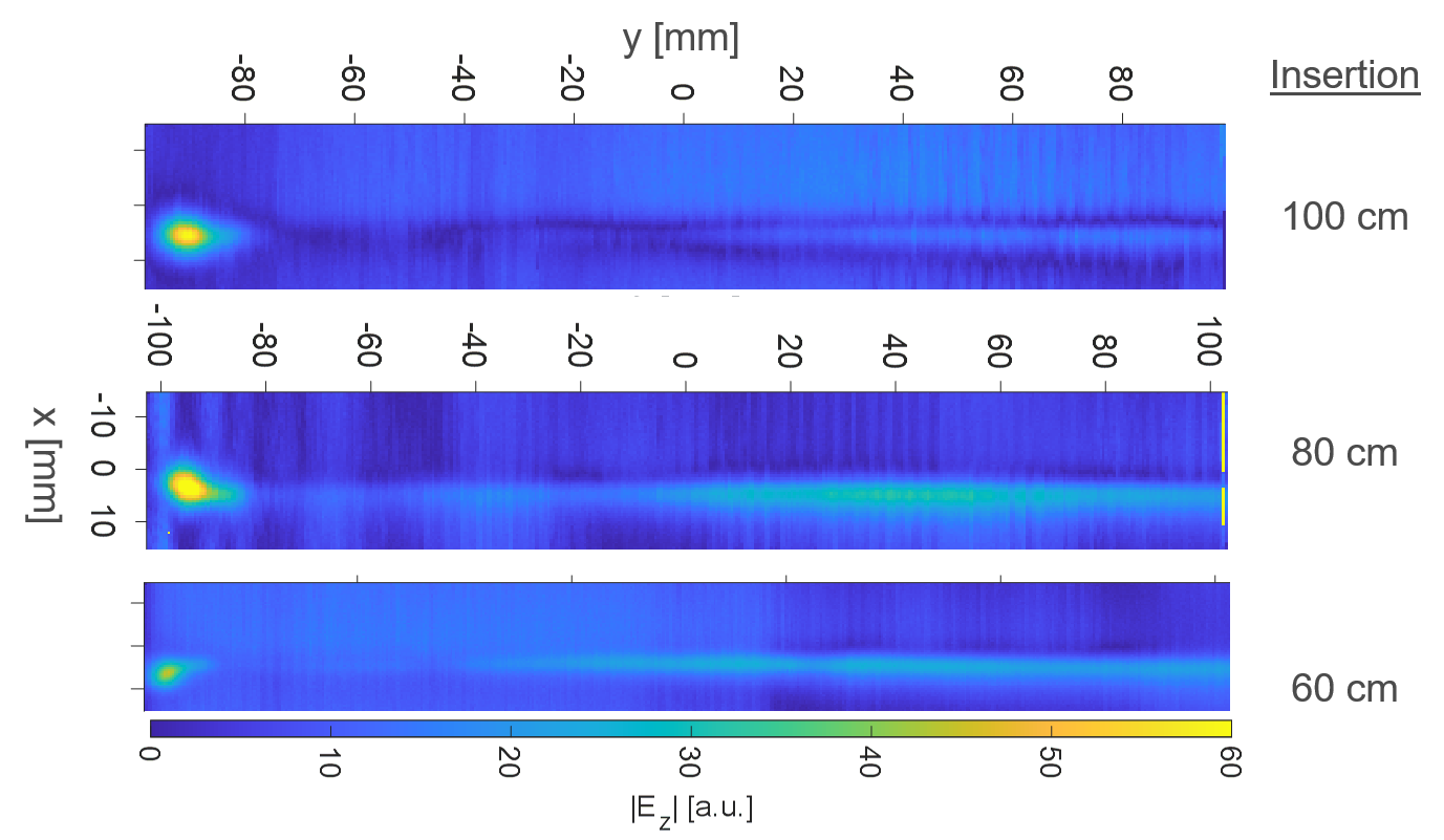
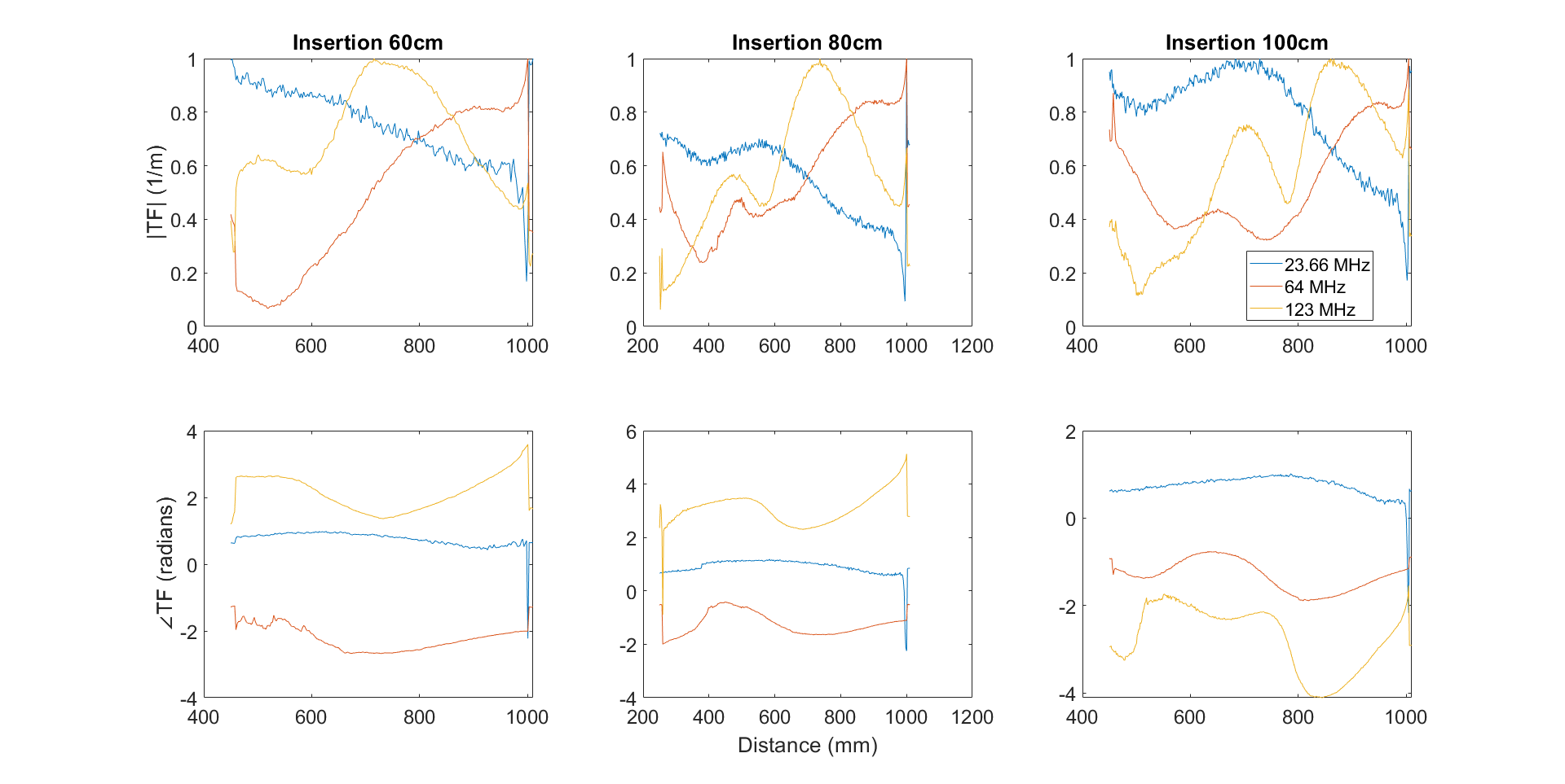
Hot spot detection: E field maps for 60, 80, and 100 cm insertion lengths are given in Fig. 1 for 23.66MHz. The hotspot is located 4mm before the tip of the AIGW at all frequencies for insertion lengths.Normalized TFs for different insertion lengths are given in Fig.2. Calibration and validation measurements were performed using two different dipole antennae, resembling the Dipole 1 and 2 in Fig.1E.
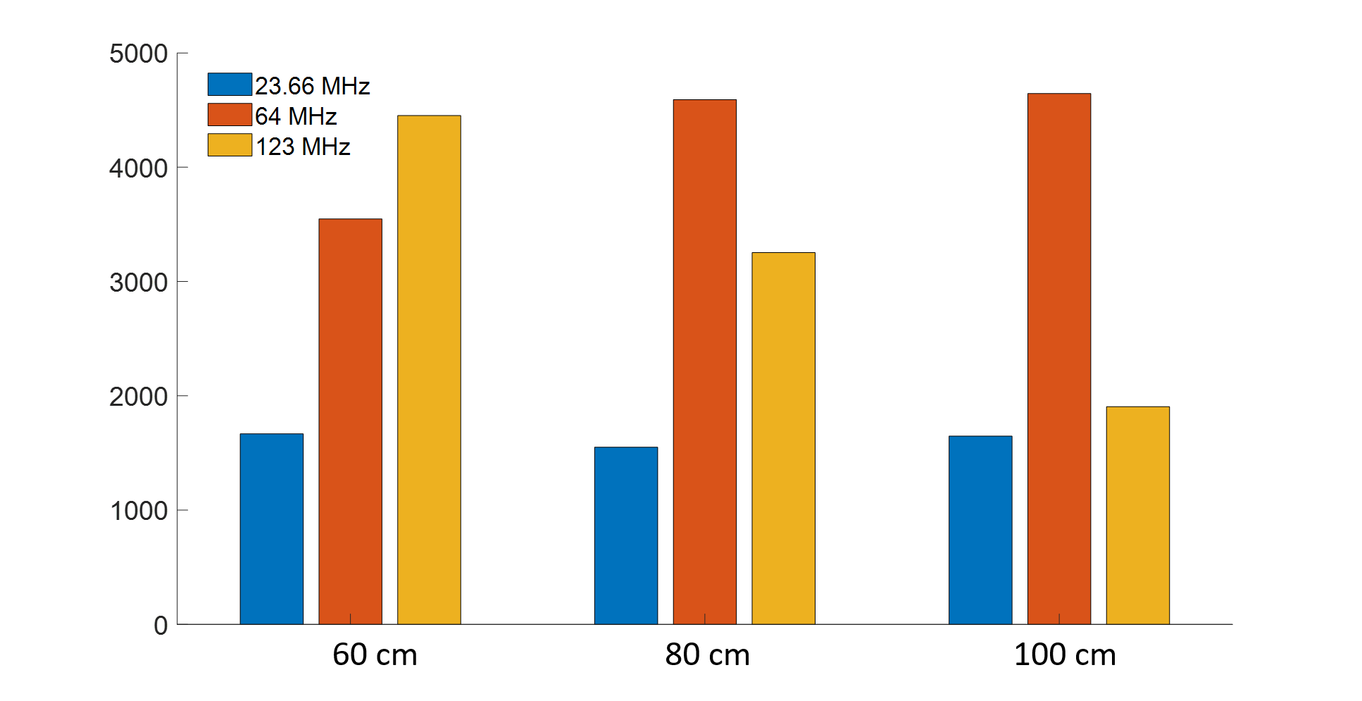
Estimated SAR values for 1kW homogeneous incident field are compared in Fig.4. 80cm insertion length results in the lowest SAR at 23.66MHz, whereas 100cm insertion length yields the lower tip SAR at 123MHz than 64MHz. For all insertion lengths, SAR is lower at 23.66 MHz.
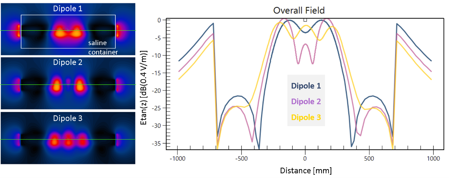
FDTD simulation results of the dipoles used for TF validation are given in Fig.5, together with the line profiles along the AIGW trajectory, which was kept as a straight line to eliminate positioning errors.
Discussion
The main advantage of the EOS measurement setup is that a single setup is used for hot spot detection, TF evaluation in cascade of different media, and validation. Performance of our setup was evaluated on an AIGW. The setup can be improved by addition of dipole sources, for example, to create circularly polarized incident fields. Recently, a test setup was proposed, which optimizes trajectories with minimal correlation of the incident E-field [9]. Etan(z) generated by different dipole antennae, as proposed in this study, are intrinsically uncorrelated, therefore ideal for validation measurements. Especially for short leads various dipole excitation patterns can be used to obtain complete and accurate validation results. Advantages of using dipole antennae for calibration and validation of TF can be listed as:- Compact source, accessible, easy to reposition and not complicated drive system
- CP, EP, LP fields can be generated using multiple dipoles driven in parallel
- Device trajectory is fixed, thus position dependent uncertainties are eliminated.
Acknowledgements
No acknowledgement found.References
[1] F. G. Shellock, “Radiofrequency Energy-Induced Heating During MR Procedures: A Review,” J. Magn. Reson. Imaging, vol. 12, no. 1, pp. 30–36, Jul. 2000, doi: 10.1002/1522-2586(200007)12:1<30::AID-JMRI4>3.0.CO;2-S.
[2] C. J. Yeung et al., “RF heating due to conductive wires during MRI depends on the phase distribution of the transmit field,” Magn. Reson. Med., vol. 48, no. 6, pp. 1096–1098, 2002, doi: 10.1002/mrm.10310.
[3] S. M. Park et al., “Calculation of MRI-induced heating of an implanted medical lead wire with an electric field transfer function,” J. Magn. Reson. Imaging, vol. 26, no. 5, pp. 1278–1285, 2007, doi: 10.1002/jmri.21159. [4] A. C. Özen et al., “Safety of active catheters in MRI: Termination impedance versus RF‐induced heating,” Magn. Reson. Med., vol. 81, no. 2, pp. 1412–1423, Feb. 2019, doi: 10.1002/mrm.27481.
[5] A. C. Özen et al., “MR safety watchdog for active catheters: Wireless impedance control with real‐time feedback,” Magn. Reson. Med., vol. 84, no. 2, pp. 1048–1060, Aug. 2020, doi: 10.1002/mrm.28153.
[6] T. Lottner et al., “A Transfer Function Measurement Setup with an Electro-optic Sensor for MR Safety Assessment in Cascaded Media,” IEEE Trans. Electromagn. Compat., pp. 1–12, 2020, doi: 10.1109/TEMC.2020.3040756.
[7] S. Reiss et al., “An optical setup for electric field measurements in MRI with high spatial resolution,” Phys. Med. Biol., vol. 60, no. 11, pp. 4355–4370, Jun. 2015, doi: 10.1088/0031-9155/60/11/4355.
[8] S. Reiss et al., “Analysis of the RF Excitation of Stents in Small Gap and Overlap Scenarios using an Electro-optical E-field Sensor,” pp. 1–20.
[9] Y. Wang et al., “A Fast and Accurate Transfer Function Validation Strategy Using Optimized Rotation-Invariant Lead Trajectories,” IEEE Trans. Electromagn. Compat., pp. 1–8, 2020, doi: 10.1109/TEMC.2020.3039488.
Figures