0363
Safe-MRI with stereo-electroencephalography (sEEG) for epilepsy patients1School of Biomedical Engineering and Imaging Sciences, King's College London, London, United Kingdom
Synopsis
Epileptic seizure investigations with sEEG electrodes are limited to regions sampled and this may exclude relevant seizure network areas. Simultaneous EEG/fMRI may better elucidate the relationship whole-brain interactions and sEEG connectivity. However, excessive radiofrequency(RF) heating of implanted electrodes is showstopper. We investigated the role of parallel-transmit(pTx) RF coil arrays at 3 Tesla to control the RF-heating and local signal increases near the electrodes using computational field simulations. The pTx coils more specifically the 16ch was more efficient than the birdcage in terms of controlling the RF-field steering in the brain, which indicated less RF-heating near the contacts of the electrodes.
Introduction
Stereo-electroencephalography (sEEG) electrodes are inserted into the brain to identify the epileptic seizure onset zone for surgery [1]. The position of the electrodes is reconstructed using computed tomography (CT) superimposed on MRI. Using two different imaging modalities can introduce errors. However, placing patients with metals into an MRI scanner can be potentially dangerous due to excessive tissue heating [2]. In addition, metals introduce artifacts on images. This work assesses the role of multi-channel parallel transmit RF coil arrays to control the excessive tissue heating and local signal increases near the SEEG electrodes using computational field simulation on realistically modelled intra-/post-surgical simultaneous MRI-EEG measurement.Methods
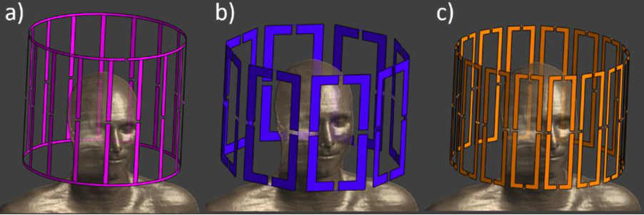
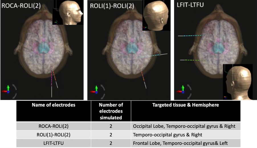
Electromagnetic field simulations using FDTD on Sim4Life 5.0 (ZMT AG, Zurich Switzerland) were performed with a human phantom model Duke [3] for 3 Tesla head birdcage in circularly-polarised mode (lowpass, 16 legs 356 mm in diameter), 8-channel (8ch) (360 mm in diameter, 250 mm long, 125 mm width/loop) and 16-channel (16ch) (similar to 8ch except 60 mm width/loop) head loop array (Fig.1). All the RF coil were placed inside cylindrical magnet bore (1560 mm in length and 752mm in diameter, modelled as PEC).Three realistic electrode configurations (Fig.2) were simulated with all coils to evaluate the B1+ and local SAR averaged over 0.1 gram tissue. A realistic model of 10-contact epilepsy/LTM spencer probe depth electrodes (SD10R-SP05X-000, Ad-Tech) with a 2.4 mm-long and 1.1 mm-diameter cylindrical contact of 47 mm recording area placed in 5 mm contact spacing and 390 mm overall depth length was included in simulations. The electrodes contain a wire within the insulator that connects all the contacts. Outside the brain within the RF coil, the wire is located parallel to the B0 field. When the electrodes were placed in the virtual human model targeting surgically relevant tissues (Fig.2), only the contacts surface and insulator are in contact with the human tissue.
Results
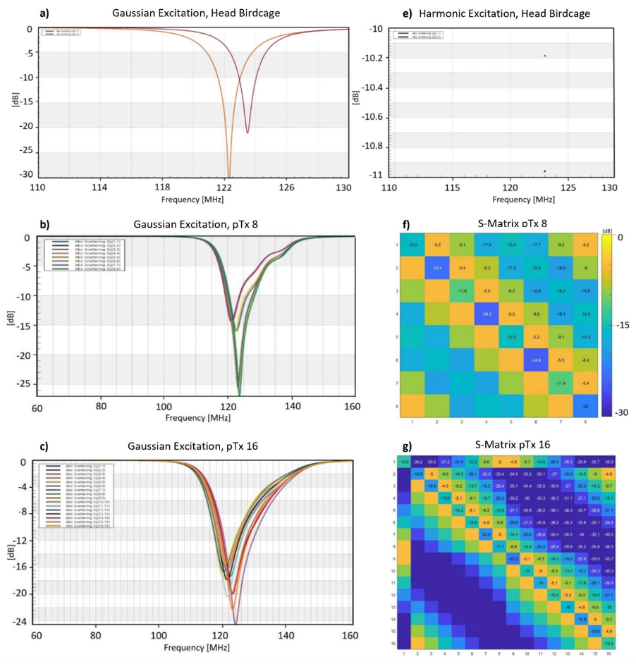
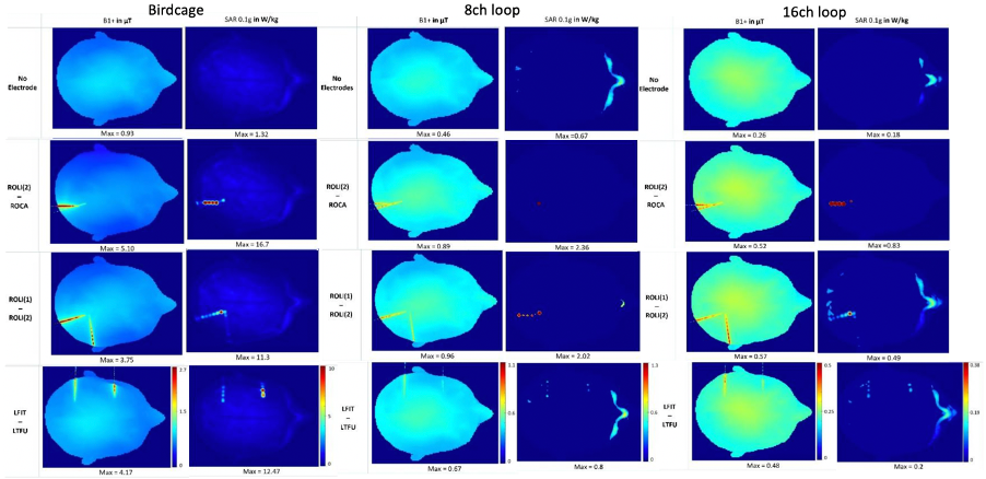
The birdcage coil (using 0.34-0.39pF in series (Cs), 32-40pF in parallel (Cp) capacitors), 8ch loop (Cs:14pF, Cp:28pF) and 16ch loop (Cs:18pF, Cp:28pF) were tuned to 123 MHz and matched to 50 Ohm with the minimum reflection coefficients of -11dB using Match Tool (Sim4Life module) with convergence of -50dB (Fig.3). Due to high next-neighbour coupling value (-5dB or better) for non-overlapping loops with gap size of 10mm and 5mm for 8ch and 16ch loop array, the absorbed power in tissue was as low as 18% and 6%, respectively compared to the 87% absorbed power in tissue for the birdcage.Fig.4 presents the maximum intensity projection in the transverse plane of the B1+ maps. When the input power was normalized to 1W total input power, B1+mean value for birdcage is 1 μT, for 8ch is 0.4 μT and for 16ch is 0.3 μT. With the electrodes inserted in the brain, B1+max is increased 4-5 times for birdcage, 1.7-1.9 times for 8ch and doubled for 16ch. Comparing to the reference model without electrode, a considerable increase of SAR0.1g,max (10 times for birdcage, 4-6 times for ptx coils) was observed near the contacts of the electrodes.
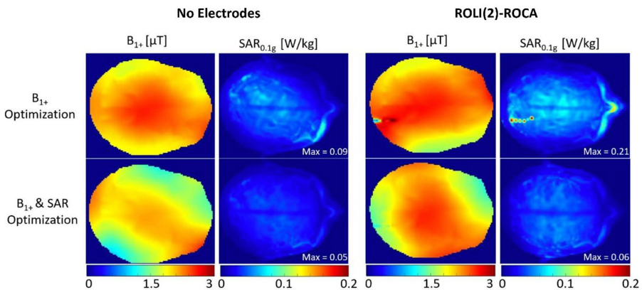
Fig.5 shows optimized B1+ and SAR maps to increase the B1 strength while aiming to decrease the SAR0.1g using static RF shimming algorithm [4]. In comparison to the B1+ maps in Fig.4, B1+mean is ten times stronger and SAR0.1g,max decreased by twice, from 0.18 to 0.09 W/kg in the absence of electrodes. When the SAR optimization was considered, the B1+ field became less homogeneous and the SAR decreased to 0.05 W/kg. After the RF shimming was evaluated with ROLI(2)-ROCA, the B1+ strength was also increased by a factor of 10. Without the SAR optimization, SAR0.1g,max decreased from 0.83 W/kg to 0.21 W/kg. With the SAR and B1+ optimization, the RF shimming algorithm completely eliminated the excessive SAR near the electrodes. The SAR0.1g,max obtained, 0.06 W/kg is comparable to the SAR obtained when optimizing the B1+ and the SAR without any electrode.
Discussion and conclusion
After choosing the electrode configuration that had the highest SAR (ROLI(2)-ROCA) on the 16ch we achieved notable results with the B1+ strength being ten times stronger than the initial one and the relative difference of B1+/√SAR0.1g,max with and without SAR optimisation was by 83.2%. Using phase-only RF shimming algorithm is very promising as it showed it could optimise B1+ and SAR in a local heating spot. Further investigations are required to explore new safety guidelines for localized brain implants with MRI in order to minimize the brain tissue damage from RF heating. Similar results were observed using pTx coils for deep brain stimulation devices [5-7]. Using a pTx coil with sEEG electrodes, the surgeons will have an improved accuracy of the localisation of the seizure onset zone to remove on epileptic patients and understanding further the mechanism of epilepsy.Acknowledgements
This work was supported by core funding from the Wellcome/EPSRC Centre for Medical Engineering [WT203148/Z/16/Z] and by the National Institute for Health Research (NIHR) Biomedical Research Centre based at Guy’s and St Thomas’ NHS Foundation Trust and King’s College London and/or the NIHR Clinical Research Facility. The views expressed are those of the author(s) and not necessarily those of the NHS, the NIHR or the Department of Health and Social Care.References
[1] Carmichael DW, Vulliemoz S, Rodionov R, et al. Simultaneous intracranial EEG–fMRI in humans: protocol considerations and data quality. Neuroimage. 2012;63(1):301-9
[2] Carmichael D. W., Thornton J. S., Rodionov R., Thornton R., McEvoy A., Allen P. J., et al., November 2008, Safety of localizing epilepsy monitoring intracranial electroencephalograph electrodes using MRI: radiofrequency-induced heating. J. Magn. Reson. Imaging 28(5), 1233–1244, https://doi.org/10.1002/jmri.21583
[3] Gosselin M, Neufeld E, Moser H. Development of a new genera-tion of high-resolution anatomical models for medical device eval-uation: The virtual population 3.0. Phys Med Biol. 2014;59:5287.
[4] Jérémie Clément, Ozlem Ipek. RF safety evaluation of an 8-channel dipole array for neonatal brain and cardiac MR at 7T parallel-transmit. MAGMA, Volume 33, page 45, S05.06 (2020)
[5] McElcheran, C.E., Golestanirad, L., Iacono, M.I. et al. Numerical Simulations of Realistic Lead Trajectories and an Experimental Verification Support the Efficacy of Parallel Radiofrequency Transmission to Reduce Heating of Deep Brain Stimulation Implants during MRI. Sci Rep 9, 2124 (2019). https://doi.org/10.1038/s41598-018-38099-w
[6] Juan Córcoles, Earl Zastrow,Niels Kuster On the estimation of the worst-case implant-induced RF-heating in multi-channel MRI. Phys. Med. Biol. 62 4711 (2017)
[7] Guerin, B, Angelone, LM, Dougherty, D, Wald, LL. Parallel transmission to reduce absorbed power around deep brain stimulation devices in MRI: Impact of number and arrangement of transmit channels. Magn Reson Med. 2020; 83: 299– 311. https://doi.org/10.1002/mrm.27905
Figures