0362
Safe scanning of elongated implants with the sensor matrix QS: Comparison of orthogonal projection and null mode based pTx mitigation1Physikalisch-Technische Bundesanstalt (PTB) Braunschweig and Berlin, Berlin, Germany
Synopsis
The sensor Q Matrix ($$$Q_S$$$) concept is introduced for safe MRI of elongated implants without compromising imaging quality. For this purpose, small and low-cost sensors, parallel transmission (pTx) and the orthogonal projection method are sufficient without the need to perform simulations, safety testing or additional MR imaging. The $$$Q_S$$$ can also be implemented along with other pTx mitigation methods such as null modes. The $$$Q_S$$$ based orthogonal projection method and the null modes method are demonstrated in testbed and MRI experiments.
Introduction
Parallel transmission (pTx) systems allow to control the RF fields around and the currents inside implants, providing RF safety along with the necessary degrees of freedom to maintain high image quality.1–6 Based on E-field and temperature information, a sensor Q Matrix $$$Q_{S}$$$ is introduced, which can be applied with small and cheap RMS sensors embedded in an implant.7,8 This safety concept does not require any simulation or MR imaging to predict, mitigate and measure RF induced heating at an implant tip in real-time. Furthermore, we investigate the $$$Q_{S}$$$ based pTx mitigation using the orthogonal projection (OP)5,9 method and the null modes (NM)2,10 approach in terms of RF-induced heating and image quality.Methods
As an implant substitute a CAT-8 cable was used and a diode (ON Semiconductor:MMDL101T1G) and a thermistor (Murata:NCP18XH103F03RB) were embedded at its uninsulated tip. The $$$Q_{S}$$$ is constructed as follows based on the sensor measurements ($$$X$$$, either RMS E-field or temperature change):$$
Q_{S,kl}^X=\ \begin{array}{l}(X_{kl}-X_{k}-X_{l})+j(X_{kl}^\dagger-X_{k}-X_{l})\;for\;k≠l\;and\;k<l\\
(X_{kl}-X_{k}-X_{l})-j(X_{kl}^\dagger-X_{k}-X_{l})\;for\;k≠l\;and\;k>l\\
\qquad\qquad\qquad\quad2X_{k}\;\;\;\;for\;k=l
\end{array}\quad,\;X\in\mathbb{R}_{>0}
$$
With $$$N^2$$$ measurements for an $$$N$$$-channel pTx system, $$$X_{kl}$$$ denotes the measured sensor values when transmitting with channel k and l and $$$X_{kl}^\dagger$$$ denotes a $$$\frac{\pi}{2}$$$ phase difference between these channels. The channels’ amplitudes are the same for all transmissions. For pTx mitigation, eigenvalues of $$$Q_{S}$$$ are computed and the corresponding Worst-Case(WC)5,9, orthogonal projection (OP)5,9 and null mode (NM)2 are determined. The pTx mitigation concept was investigated in an implant-safety testbed7 at 300 MHz (Figure-1A) and inside a 3T scanner (Figure-1B).
Testbed Experiments
Diode based pTx mitigation ($$$Q_S^E$$$)
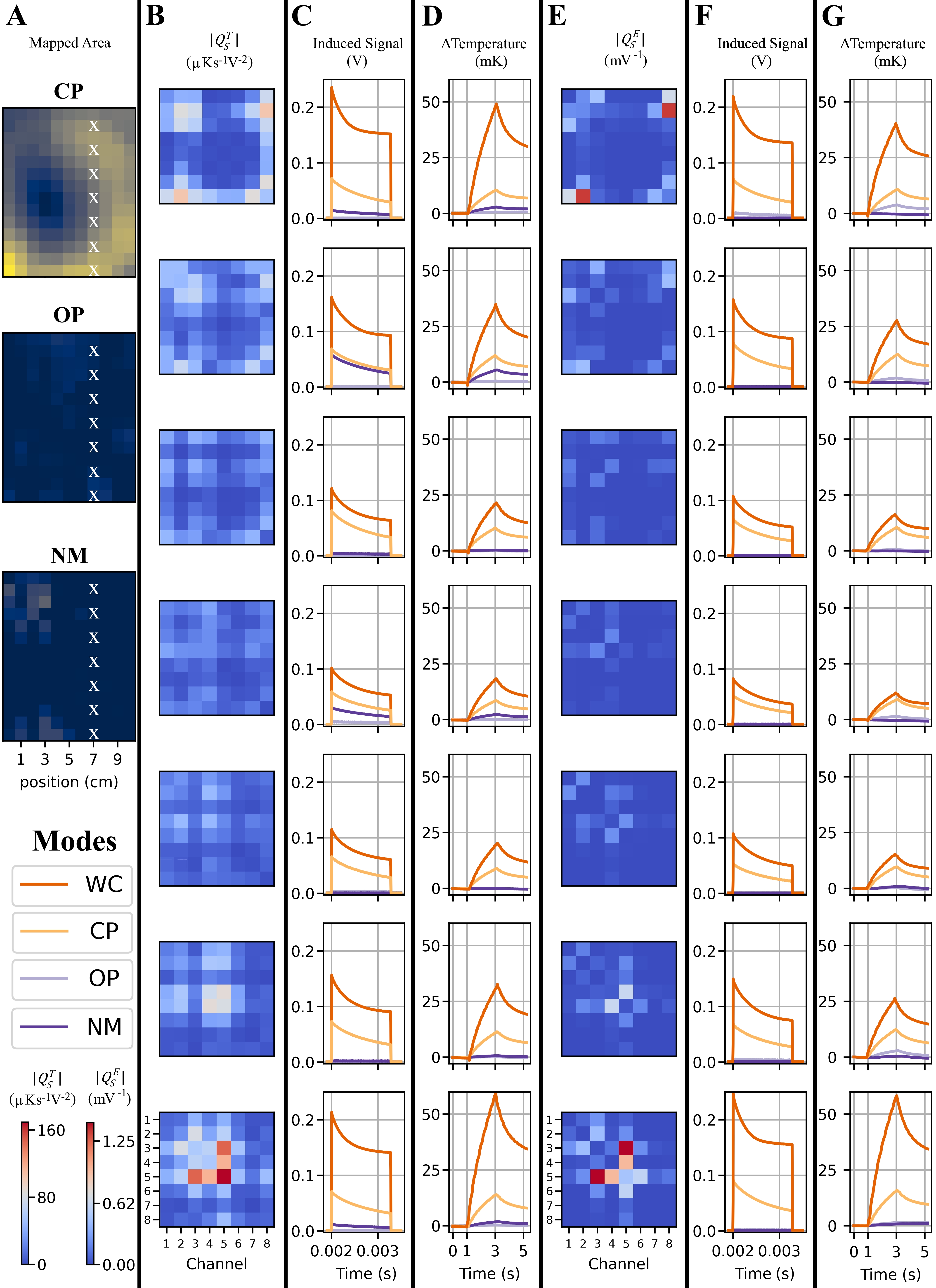
An automated 8-channel pTx experiment with diode based $$$Q_S^E$$$ acquisition and pTx mitigation was performed in a 2D area (140mm×110mm, 10 mm steps) at 154 implant locations. At every location six measurements using three pTx modes (CP, OP and NM) (Pfwd=2.86W) were performed:
- Measurement of the RF-induced steady-state diode signals during RF transmission ($$$3\times1.26\,ms$$$).
- Measurement of the RF-induced heating rate using a thermistor during RF transmission ( $$$3\times2\,s$$$).
At 7 of the aforementioned 154 locations, thermistor based $$$Q_S^T$$$ acquisition ($$$0.5\,s$$$ RF heating and $$$0.5\,s$$$ cooling per measurement, total acquisition time $$$8\times8\times1\,s=64\,s$$$ per location) and pTx measurements were performed. The aforementioned 6 measurements were repeated, now with OP and NM calculated based on $$$Q_S^T$$$.
MRI Experiments
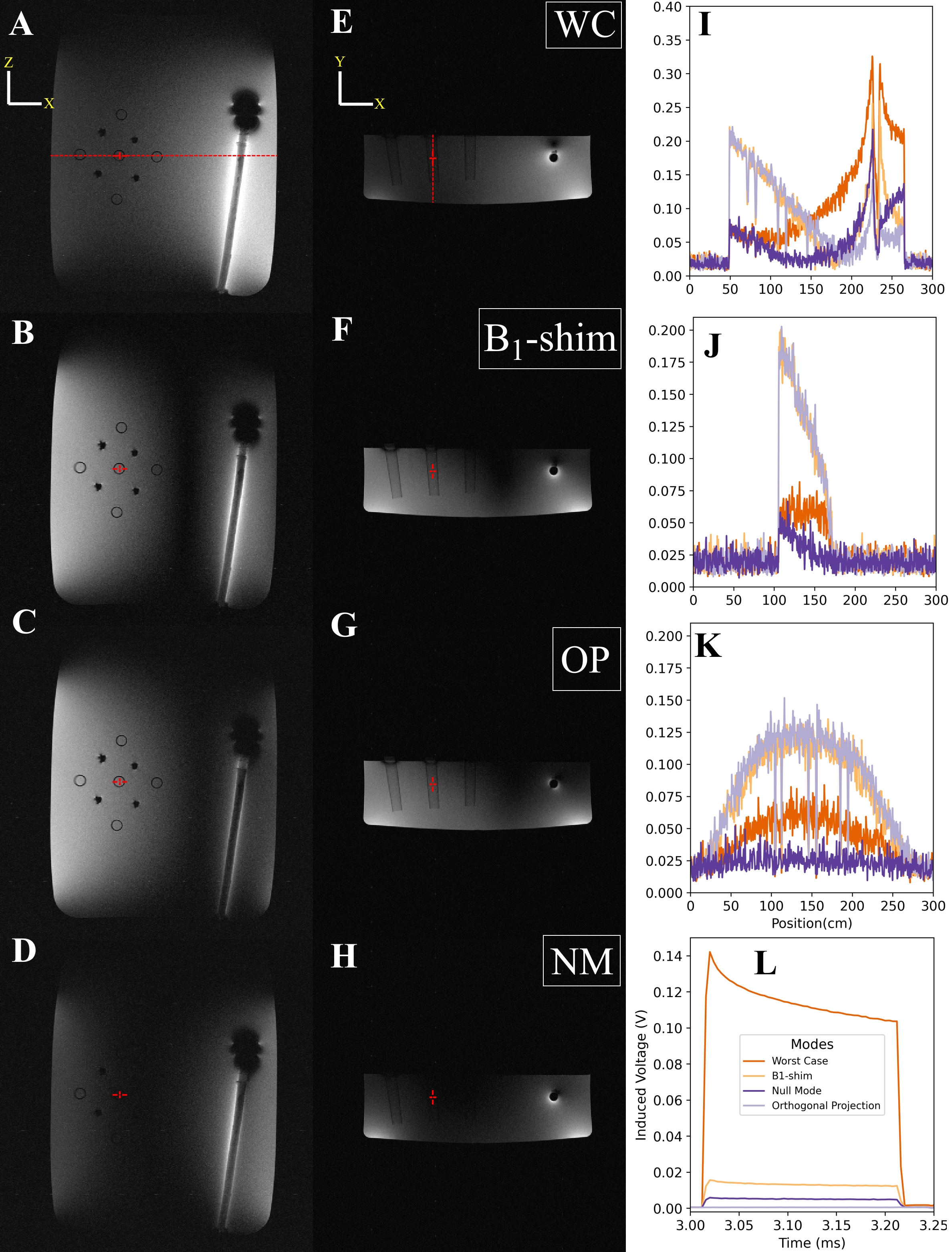
The implant substitute was embedded in a rectangular PVP phantom together with 9 plastic tubes placed next to the implant. The tubes are chosen to mimic contrast and resemble a situation where diagnostic imaging is required outside the implant region. At the central tube, $$$B_1^+$$$ was maximized by adjusting the phase (same amplitude per channel) based on previously acquired $$$B_1$$$-maps; this is referred to as the B1-shim transmission mode. This setup was positioned inside an 8‐channel pTx RF coil (RAPID Biomedical) and a 3T scanner.$$$Q_S^E$$$ was acquired using an FID sequence of 64 pulses of 200µs. The OP mode was obtained by projecting the aforementioned B1-shim on the WC-orthogonal subspace.5,9 Then, GRE images were acquired for all excitation schemes (WC, B1-shim, OP, NM) using the same total forward power.
Results
Testbed ExperimentsDiode based pTx mitigation
The results for the 154 implant locations are shown in Figure-3. The $$$Q_S^E$$$ acquisition and mitigation is real-time capable (acquisition and mitigation $$$\sim 20\,ms$$$), and OP was able to reduce RF induced heating in all locations, while for NM two locations were unsuccessful (<1% higher than CP). OP and NM reduced the voltage signals by factors $$$\geq\,2$$$ in 99% and 93%, respectively, of the mapped area compared to CP mode (Figure-3C). RF heating correlated well to the sensor readings (Figure-3B). NM transmission showed lower induced signals in 62% of the locations compared to OP (Figure-3C).
Thermistor based pTx mitigation
The results for the seven implant locations are shown in Figure-4. pTx mitigation was successful for OP and NM compared to WC and CP for all locations. For OP, thermistor-based mitigation gave slightly better results compared to the diode sensor.
MRI Experiments
For WC and B1-shim, the signal intensity along the implant increases, indicating stronger coupling compared to OP and NM (Figure-5). This is confirmed by the measured diode voltages, which could be reduced substantially by both OP and NM. Despite successfully suppressed RF heating, image quality produced by the OP mode is comparable to the B1-shim setting in the target area.
Discussion and Conclusion
This work demonstrates how cheap (<1€) and small (<1.5mm3) RMS sensors can be used to substantially reduce the risk for RF-induced heating in an implant by using $$$Q_{S}$$$-based pTx mitigation. This concept was successfully demonstrated in 155 different locations and 932 pTx excitations for a 300-MHz testbed and inside a 3T MRI. Only the RMS tip sensor signal was needed to obtain these results; no simulations, imaging techniques or ex ante safety testing was required. The method works in real-time and the sensors can also be used as an additional fast and sensitive safety watchdog.11 Both OP and NM mitigation methods show comparable results in terms of RF induced heating reduction, while the OP mode gives better imaging quality in regions outside the implant.Acknowledgements
This project (17IND01 MIMAS) has received funding from the EMPIR programme co-financed by the Participating States and from the European Union's Horizon 2020 research and innovation programme.References
1. Eryaman Y, Akin B, Atalar E. Reduction of implant RF heating through modification of transmit coil electric field. Magn Reson Med. 2011;65(5):1305-1313. doi:10.1002/mrm.22724
2. Etezadi-Amoli M, Stang P, Kerr A, Pauly J, Scott G. Controlling radiofrequency-induced currents in guidewires using parallel transmit. Magn Reson Med. 2015;74(6):1790-1802. doi:10.1002/mrm.25543
3. Silemek B, Acikel V, Oto C, et al. A temperature sensor implant for active implantable medical devices for in vivo subacute heating tests under MRI. Magn Reson Med. 2018;79(5):2824-2832. doi:10.1002/mrm.26914
4. McElcheran CE, Golestanirad L, Iacono MI, et al. Numerical Simulations of Realistic Lead Trajectories and an Experimental Verification Support the Efficacy of Parallel Radiofrequency Transmission to Reduce Heating of Deep Brain Stimulation Implants during MRI. Sci Rep. 2019;9(1):1-14. doi:10.1038/s41598-018-38099-w
5. Winter L, Silemek B, Petzold J, et al. Parallel transmission medical implant safety testbed: Real-time mitigation of RF induced tip heating using time-domain E-field sensors. Magn Reson Med. 2020;84(6):3468-3484. doi:https://doi.org/10.1002/mrm.28379
6. Guerin B, Angelone LM, Dougherty D, Wald LL. Parallel transmission to reduce absorbed power around deep brain stimulation devices in MRI: Impact of number and arrangement of transmit channels. Magn Reson Med. 2020;83(1):299-311. doi:10.1002/mrm.27905
7. Silemek B, Winter L, Seifert F, Pfeiffer H, Ittermann B. Measurement-based safety assessment, prediction and mitigation of RF induced implant heating with parallel transmission: temperature matrix. 28th Annual Meeting of ISMRM. ; 2020:1135.
8. Silemek B, Winter L, Seifert F, et al. Real-time safety assessment and mitigation of RF induced implant heating with parallel transmission and low-cost RMS sensors. 28th Annual Meeting of ISMRM. ; 2020:4196.
9. Seifert F, Weidemann G, Ittermann B. Q matrix approach to control implant heating by transmit array coils. 23rd Annual Meeting of ISMRM. ; 2015:3212.
10. Godinez F, Scott G, Padormo F, Hajnal JV, Malik SJ. Safe guidewire visualization using the modes of a PTx transmit array MR system. Magn Reson Med. 2020;83(6):2343-2355. doi:10.1002/mrm.28069
11. Özen AC, Silemek B, Lottner T, Atalar E, Bock M. MR safety watchdog for active catheters: Wireless impedance control with real‐time feedback. Magn Reson Med. Published online January 21, 2020:mrm.28153. doi:10.1002/mrm.28153
12. Han H, Moritz R, Oberacker E, Waiczies H, Niendorf T, Winter L. Open Source 3D Multipurpose Measurement System with Submillimetre Fidelity and First Application in Magnetic Resonance. Sci Rep. 2017;7(1):13452. doi:10.1038/s41598-017-13824-z
Figures
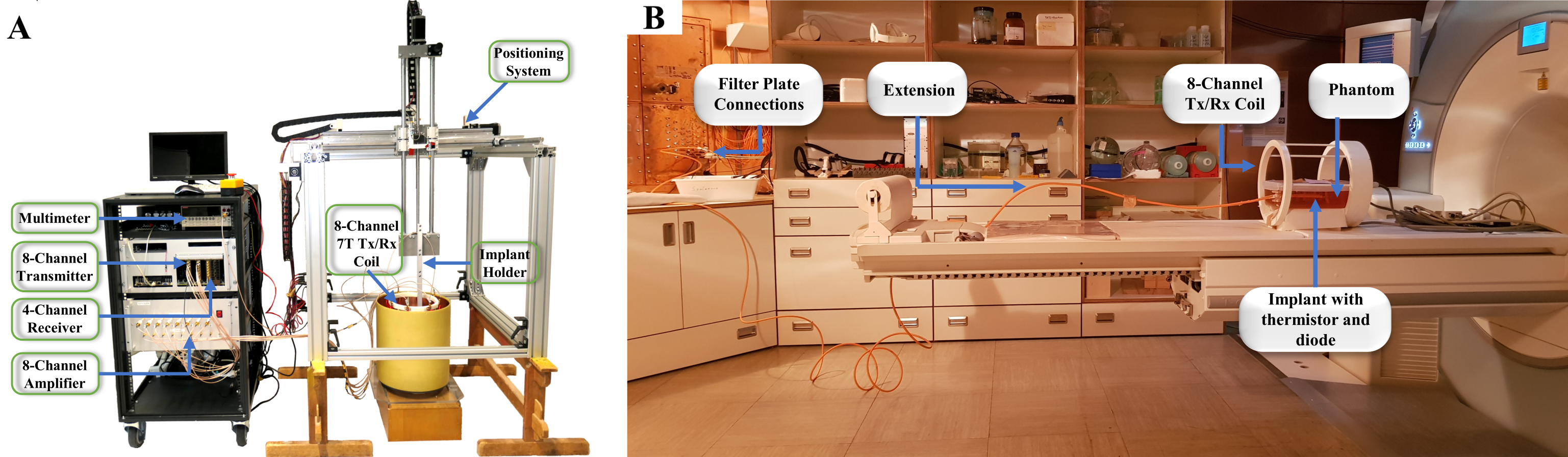
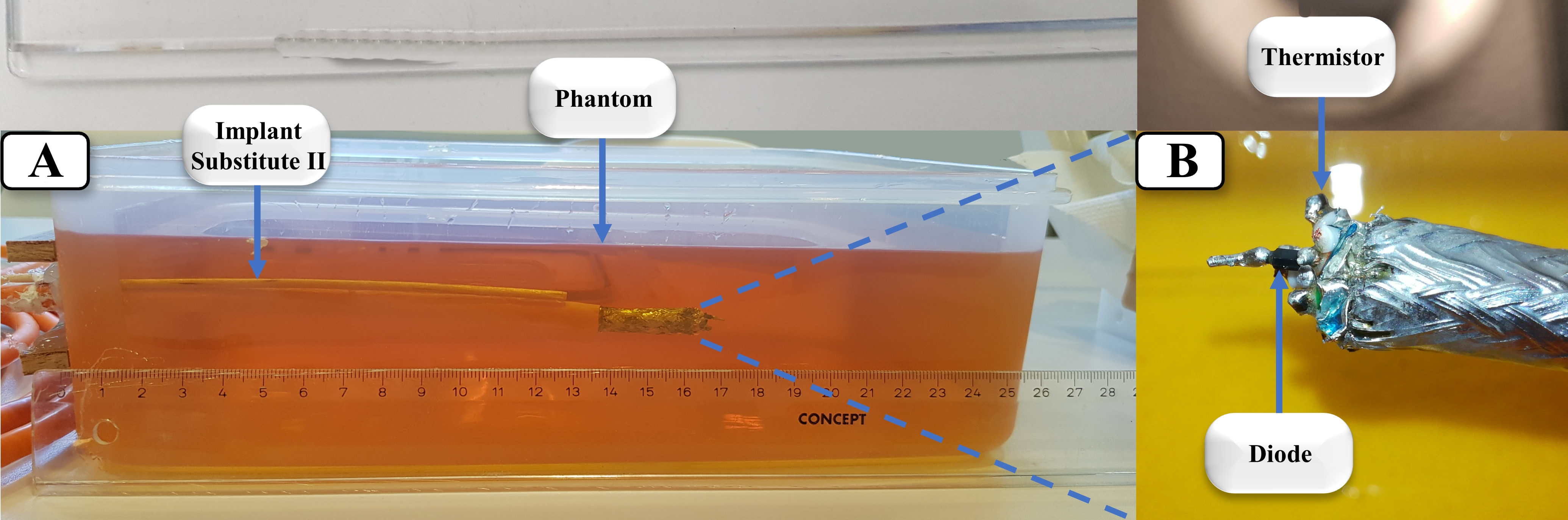
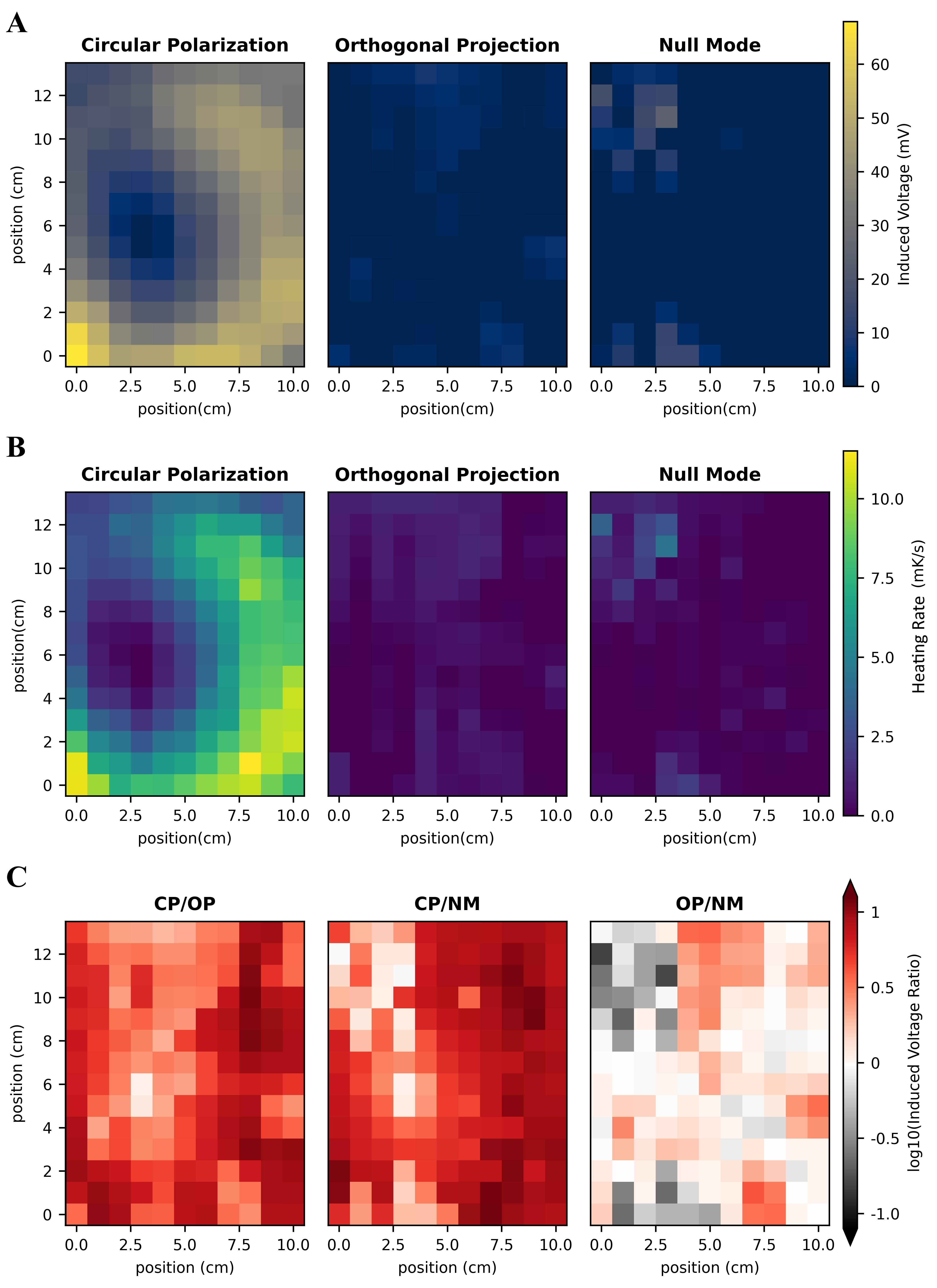
Figure-3: Results for the diode sensor in the mapped area in the testbed. The implant is immersed 120 mm into the phantom. (A) The diode readings for CP, OP and NM. OP and NM are derived from eigenvalues of the acquired $$$Q_S^E$$$. In (B), the heating rates measured by the thermistor are mapped, when the same CP, OP and NM are applied for 2 s per implant position. (C) Diode-signal (i.e. E-field) ratios (logarithmic scale) for each mode, indicating improved or reduced patient hazard. Compared to CP, both OP and NM reduce the E-field nearly everywhere (99%) and by a factor ≥2 in 93% of the positions.