0360
Safe 7T MRI of tissues neighboring Mg-based biodegradable implants using parallel transmission1MRI.TOOLS GmbH, Berlin, Germany, 2Berlin Ultrahigh Field Facility (B.U.F.F.), Max Delbrück Center for Molecular Medicine in the Helmholtz Association, Berlin, Germany
Synopsis
Bio-degradable implants have the benefit of eliminating implant removal surgery. Yet, it’s essential to monitor the implant and tissue\bone after implementation. MRI monitoring in the vicinity of the implant might be compromised by tissue heating and transmission field inhomogeneities. To address these challenges here an RF transceiver array is designed, manufactured and evaluated aiming to facilitate 7T MRI in the vicinity of implants. For this purpose, EMF simulations are performed to derive an optimum excitation vector that reduces local RF power deposition while ensuring a proper B1+-field. The RF array is evaluated in phantom experiments and benchmarked with the simulations.
Introduction
Bio-degradable Mg-based implants1 promote patient comfort by eliminating implant removal surgery. Post implantation, the degradation kinetics of the Mg alloys might vary for different environments/patients. Therefore the healing process of the surrounding bone/tissues and the corrosion state of the implants need to be monitored2. MRI may be exploited to examine the degradation status of biodegradable implants and to study the implant/tissue interface3. The metallic nature of conductive Mg implants constitutes challenges for MRI. This includes 1) MR safety risks due to the elevation of the specific absorption rate (SAR) in the vicinity of implant4 and 2) B1 field inhomogeneities caused by interferences of the radio frequency (RF) field with the implant. These constraints can be offset by leveraging the degrees of freedom facilitated by parallel transmission using multichannel RF coil arrays. Recognizing this opportunity, this work examines the applicability of RF array configurations for safe MRI of biodegradable implants at 7.0T. For this purpose RF array configurations comprising loop elements and/or fractionated-dipoles5 are characterized in electromagnetic field simulations using the metrics peak-SAR10g and transmission field uniformity to derive optimum B1 shim patterns using genetic algorithm (GA). The results are benchmarked against the birdcage mode6 (CP) and the orthogonal projection method7 (OP) in simulations and in a phantom study with a focus on B1+, specific absorption rate (SAR) and temperature maps.Methods
EMF simulations were performed (CST Studio Suite 2020, CST MWS, Darmstadt, Germany) for three cylindrical array configurations of: (i) 8 loop elements, (ii) 8 dipoles, (iii) 8 building blocks comprising a loop and a dipole element8. The evaluation focused on achievable implant SAR reduction and homogenization of B1+ in a cylindrical (r=20mm and L=110mm) region of interest (ROI) around the implant. EMF shimming was optimized using a multi-objective genetic algorithm that calculates the tradeoff-curve of B1 homogeneity in the ROI vs. the implant SAR. The outcome of the GA was benchmarked against CP and OP shimming patterns. In simulations, a cylindrical phantom (r=85mm and L=300mm) mimicking muscle electrical properties at 297.2 MHz was used. The same PVP-based phantom9 was used for the experiments A 70mm long copper wire with 1mm radius was used to mimic an implant and aligned in parallel with the phantom at a 30mm distance from its surface. The RF modules were positioned with 20mm distance from the phantom and shielded with 30mm distance from the elements. Phantom experiments were performed on a 7T MRI scanner (SIEMENS Magnetom) where the RF transceiver array was connected to the scanner through an interface (MRI.TOOLS GmbH, Germany) to utilize the pTx mode. B1+ maps were acquired using a fast gradient-echo imaging with pre-saturation10. Characterization of implant heating was conducted with SAR mapping (simulations) and temperature mapping (experiments) using a high-power heating regime (Pavearage=175W, t=5 min).Result
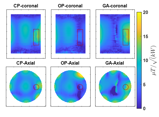
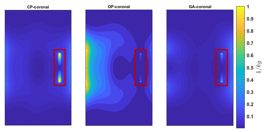
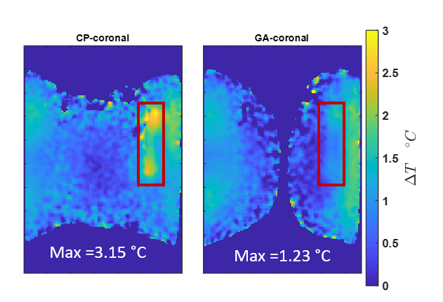
Our EMF simulations revealed that an array of 8 RF building blocks comprising a loop and dipole element as shown in figure 1 is the superior design. We obtained excellent agreement between the measured and simulated B1+ maps as outlined in figure 2 and 3, respectively. The GA approach outperforms the CP and OP in the ROI in terms of both B1+ magnitude and homogeneity as well as SAR efficiency. Statistical parameters of the simulated B1+ in the ROI are presented in the table of figure2. The SAR maps of CP, OP and GA maps are presented in figure 4 and the CP and GA temperature maps in figure 5. The simulated value of maximum average SAR10g (normalized to 1W excitation) in the whole phantom using CP, OP and GA is 0.2 $$$ {1}/{kg}$$$ , 0.31 $$$ {1}/{kg}$$$ and 0.24 $$$ {1}/{kg}$$$, respectively. For the CP mode, the maximum is found at the implant, whereas for both OP and GA excitation, peak SAR occurs at the surface. Even though overall peak SAR for unit power is slightly increased comparing GA to CP excitation, B1+ in the ROI is also significantly increased, leading to $$${B^+_1}/{\sqrt {SAR_{Max}}}$$$ efficiencies of 0.54 $$${\mu T}/{\sqrt {{W}/{kg}}}$$$ and 0.67 $$${\mu T}/{\sqrt {{W}/{kg}}}$$$ for CP and GA, respectively, i.e. showing a 24% efficiency increase. While OP can significantly reduce implant SAR, it nevertheless suffers from a peak SAR increase of more than 50%. On the other hand, the GA method successfully limits both implant as well as overall peak SAR while still delivering improved B1 in the ROI. The maximum temperature increment in the experiment using GA is 61% lower compared to CP.Discussion
CP excitation leads to B1 artifacts close to the implant as well as excessive local RF power deposition. The orthogonal projection method reduces implant heating but suffers from B1 degradation in the implant vicinity as well as excessive peak SAR increase outside the implant region. Our results demonstrate that the multi-objective GA approach affords SAR reduction in conjunction with a strong and uniform B1+ field in the implant region.Conclusion
Parallel transmission using the proposed 8-channel RF array in conjunction with the GA approach helps to meet the requirements of MR safety and transmission field uniformity to support MRI based monitoring of tissue healing and for the benefit of MRI characterization of the degradation state of bio-degradable implants.Acknowledgements
This project is supported by the H. 2020 European Training Network of the European Union (MgSafe, grant agr. No. 811226)References
[1] B. J. C. Luthringer, F. Feyerabend, and R. W. Römer, “Magnesium-Based Implants: A Mini-Review,” Magnesium Research. 2014, doi: 10.1684/mrh.2015.0375. [2] A. Myrissa et al., “In vitro and in vivo comparison of binary Mg alloys and pure Mg,” Materials Science and Engineering C, 2016, doi: 10.1016/j.msec.2015.12.064. [3] D. Paramitha, M. F. Ulum, A. Purnama, D. H. B. Wicaksono, D. Noviana, and H. Hermawan, “Monitoring degradation products and metal ions in vivo,” in Monitoring and Evaluation of Biomaterials and their Performance In Vivo, 2017. [4] L. Winter, F. Seifert, L. Zilberti, and M. Murbach, “MRI-Related Heating of Implants and Devices : A Review Physics of Implant Heating,” pp. 1–20, 2020, doi: 10.1002/jmri.27194. [5] A. J. E. Raaijmakers et al., “The fractionated dipole antenna: A new antenna for body imaging at 7 Tesla,” Magnetic Resonance in Medicine, 2016, doi: 10.1002/mrm.25596. [6] V. Alagappan et al., “Degenerate mode band-pass birdcage coil for accelerated parallel excitation,” Magnetic Resonance in Medicine, 2007, doi: 10.1002/mrm.21247. [7] L. Winter et al., “Parallel transmission medical implant safety testbed: Real-time mitigation of RF induced tip heating using time-domain E-field sensors,” Magnetic Resonance in Medicine, 2020, doi: 10.1002/mrm.28379. [8] M. A. Ertürk, A. J. E. Raaijmakers, G. Adriany, K. Uğurbil, and G. J. Metzger, “A 16-channel combined loop-dipole transceiver array for 7 Tesla body MRI,” Magnetic Resonance in Medicine, 2017, doi: 10.1002/mrm.26153. [9] S. Chung, D. Kim, E. Breton, and L. Axel, “Rapid B1+ mapping using a preconditioning RF pulse with turboFLASH readout,” Magnetic Resonance in Medicine, 2010, doi: 10.1002/mrm.22423.Figures
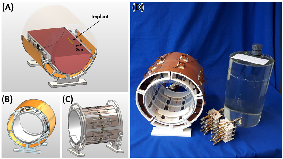
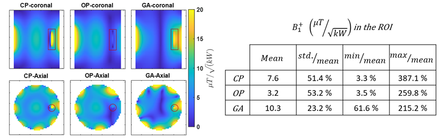
Figure 2; left image) simulation results of coronal (top row) and transversal (bottom row) B1+ maps at the center of the implant corresponding to degenerate birdcage (CP), orthogonal projection (OP) and genetic algorithm-based (GA) shimming. The CP mode displays a large inhomogeneity with complete B1 voids around the implant. This void is even pronounced for OP excitation. Our GA approach eliminates B1 voids in the region to allow imaging. Right table) Summary of the statistics obtained for the B1+ field in the ROI.