0358
Demystifying the effect of field strength on RF heating of conductive leads: A simulation study of SAR in DBS lead models during MRI at 1.5 T - 10.5 T1Electrical and Electronics Engineering Department, Bilkent University, Ankara, Turkey, 2National Magnetic Resonance Research Center (UMRAM), Bilkent University, Ankara, Turkey, 3Department of Radiology, Feinberg School of Medicine, Northwestern University, Chicago, IL, United States, 4Center for Magnetic Resonance Research (CMRR), University of Minnesota, Minneapolis, MN, United States, 5Institute of Medical Physics and Radiation Protection, Mittelhessen University of Applied Sciences, Giessen, Germany, 6Department of Biomedical Engineering, McCormick School of Engineering, Northwestern University, Evanston, IL, United States
Synopsis
We examined the effect of magnetic field strength, and by proxy RF resonance frequency, on RF heating of deep brain stimulation (DBS) lead models during RF exposure covering frequencies from 64MHz (1.5T) to 447MHz (10.5T). We report 1g-SAR at the tips of a cohort of 33 DBS implant models with realistic trajectories when the input power of RF coils was adjusted to impose safety limits based on either B1+ or global head SAR. We observed that coils with higher resonance frequency generated a lower 1g-SAR around implanted leads when the global head SAR was kept constant across different coils.
Introduction
With the growing prevalence of high and ultra-high field MRI and the upward trend in indication for electronically active implantable medical devices (AIMDs), the number of patients with AIMDs who are in need of MRI has increased substantially. In this regard, RF heating of the tissue around implanted leads is a major safety concern. A common misunderstanding in the field is that scanners at higher field strength are in general, more dangerous in terms of local implant heating. Recent studies comparing RF heating of deep brain stimulation (DBS) devices at 1.5 T and 3 T, however, have shown otherwise1. Here we report the results of a simulation study with 33 patient-derived models of DBS leads exposed to RF fields in a range of frequencies corresponding to 1.5 T-10.5 T and compare the local SAR at lead tips for different exposure limits. We found that when the global head SAR is set to determine the upper safety limit, coils with higher resonance frequency generate lower local SAR around implanted leads. In contrast, when the B1+ is kept constant across different field strengths, RF coils with higher resonance frequency generate higher local SAR around implanted leads. Our results indicate that ultra-high field MRI is not necessarily more dangerous in patients with conductive implants compared to MRI at lower fields.Methods
Four RF head coil models were constructed and tuned to respective proton Larmor frequencies at 1.5 T, 3 T, 7 T, and 10.5 T (64 MHz for 1.5 T, 127 MHz for 3 T, 297 MHz for 7 T, and 447 MHz for 10.5 T). Coil geometries were based on physical prototypes built in our labs. These included 16-rung low-pass birdcage coils at 1.5 T2 and 3 T3, a 16-rung hybrid birdcage coil at 7 T4, and an 8-channel bumped dipole array at 10.5 T5 (Figure 1). All coils were driven in the circularly-polarized (CP) excitation mode.A total of 33 DBS lead models with realistic trajectories were constructed from postoperative computed tomography (CT) images of patients with deep brain stimulation implants. Details of DBS lead model construction is described in our earlier works6-9 (Figure 2). Each lead was made of four electrode contacts connected via a solid straight platinum core (diameter = 0.26 mm and σ = 9.3×10⁶ S/m), embedded in an insulator made of urethane (diameter = 1.27 mm and εr = 3.5). Lead models were incorporated into a standard homogeneous head model (σ = 0.49 S/m and εr = 66). Simulations were implemented in ANSYS Electronics Desktop 19.2 (ANSYS Inc., Canonsburg, PA). The maximum 1g-averaged SAR (1g-SARmax) was calculated and reported within a cubic volume (20×20×20 mm3) surrounding DBS lead contacts. The mean value of 1g-SARmax was compared among different coils when total input power was adjusted to impose two different safety limits: 1) An average B1+ = 2 μT on an axial plane passing through patient's forehead, and 2) A global head SAR (GHSAR) of 3 W/kg in the head phantom.
Results
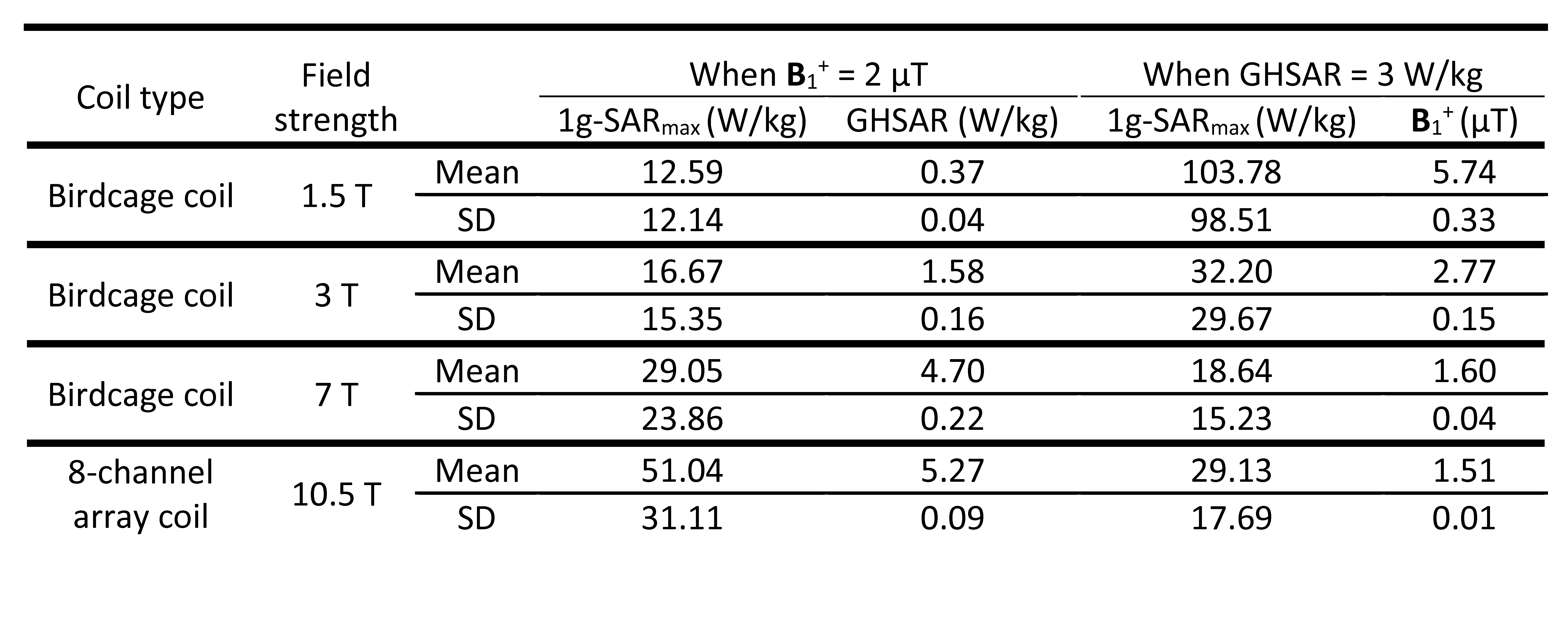
Figure 3 illustrates an example of the local SAR distribution (ID10) over an axial plane passing through the electrode contacts for all four RF coils. Figure 4A shows the box plots of the 1g-SARmax and GHSAR over all 33 DBS lead models when the mean of B1+ was kept constant. The results showed an upward trend in the mean of the 1g-SARmax, with 1g-SARmax = 13±12 W/kg at 1.5 T, 17±16 W/kg at 3 T, 29±24 W/kg at 7 T, and 51±31 W/kg at 10.5 T (Table 1). This indicates that when B1+ is chosen to set the upper safety limit for MRI, coils with higher resonance frequency generate higher local SAR around implanted leads. Figure 4B demonstrates the box plots of the 1g-SARmax and the mean of the B1+ for the constant GHSAR. In contrast to the former case, the median of both 1g-SARmax and B1+ show a general downward trend with increasing the field strength. The mean ± standard deviation of 1g-SARmax was 104±99 W/kg for the 1.5 T coil, 32±30 W/kg for the 3 T coil, 19±15 W/kg for the 7 T coil, and 29±18 W/kg for the 10.5 T coil (Table 1). This means that if the global head SAR is chosen to set the upper safety limit during MRI, coils with higher resonance frequency generate less local SAR around conductive implants. Although counter intuitive, this result is in agreement with recent experimental reports comparing RF heating of DBS devices at 1.5 T and 3 T1.Conclusion and Discussion
Since the advent of MRI, there have been strong incentives to perform MRI at ever higher magnetic fields. Although increasing the magnetic field strength increases the signal-to-noise ratio substantially10, RF safety in ultra-high fields remains challenging compared to low-field imaging. This is partially because increased static field contributes to shorter wavelengths and formation of field hot-spots in the tissue11, 12. However, higher fields are not necessarily more dangerous in terms of implant heating, and indeed, when the global SAR limit is kept constant as the upper limit, coils at higher resonance frequency generate less local SAR due to decreased B1+ levels.Acknowledgements
No acknowledgement found.References
1. Bhusal B, Nguyen BT, Sanpitak PP, et al. Effect of Device Configuration and Patient's Body Composition on the RF Heating and Nonsusceptibility Artifact of Deep Brain Stimulation Implants DuringMRIat 1.5T and 3T. J Magn Reson Imaging. 2020.
2. Golestanirad L, Kazemivalipour E, Keil B, et al. Reconfigurable MRI coil technology can substantially reduce RF heating of deep brain stimulation implants: First in-vitro study of RF heating reduction in bilateral DBS leads at 1.5 T. Plos One. 2019;14(8).
3. Golestanirad L, Kirsch J, Bonmassar G, et al. RF-induced heating in tissue near bilateral DBS implants during MRI at 1.5 T and 3T: The role of surgical lead management. Neuroimage. 2019;184:566-576.
4. Golestanirad L, Angelone LM, Kirsch J, et al. Reducing RF-Induced Heating Near Implanted Leads Through High-Dielectric Capacitive Bleeding of Current (CBLOC). Ieee T Microw Theory. 2019;67(3):1265-1273.
5. Sadeghi-Tarakameh A, DelaBarre L, Lagore RL, et al. In vivo human head MRI at 10.5T: A radiofrequency safety study and preliminary imaging results. Magn Reson Med. 2020;84(1):484-496.
6. Golestanirad L, Angelone LM, Iacono MI, et al. Local SAR near deep brain stimulation (DBS) electrodes at 64 and 127 MHz: A simulation study of the effect of extracranial loops. Magn Reson Med. 2017;78(4):1558-1565.
7. McElcheran CE, Golestanirad L, Iacono MI, et al. Numerical Simulations of Realistic Lead Trajectories and an Experimental Verification Support the Efficacy of Parallel Radiofrequency Transmission to Reduce Heating of Deep Brain Stimulation Implants during MRI. Sci Rep-Uk. 2019;9.
8. Golestanirad L, Kazemivalipour E, Lampman D, et al. RF heating of deep brain stimulation implants in open-bore vertical MRI systems: A simulation study with realistic device configurations. Magn Reson Med. 2020;83(6):2284-2292.
9. Kazemivalipour E, Keil B, Vali A, et al. Reconfigurable MRI technology for low-SAR imaging of deep brain stimulation at 3T: Application in bilateral leads, fully-implanted systems, and surgically modified lead trajectories. Neuroimage. 2019;199:18-29
10. Cao ZP, Park J, Cho ZH, et al. Numerical Evaluation of Image Homogeneity, Signal-to-Noise Ratio, and Specific Absorption Rate for Human Brain Imaging at 1.5, 3, 7, 10.5, and 14T in an 8-Channel Transmit/Receive Array. J Magn Reson Imaging. 2015;41(5):1432-1439.
11. Ocali O, Atalar E. Ultimate intrinsic signal-to-noise ratio in MRI. Magn Reson Med. 1998;39(3):462-473.12. Raaijmakers AJE, Steensma BR. Local SAR Assessment for Multitransmit Systems: A Study on the Peak Local SAR Value as a Function of Magnetic Field Strength. Emagres. 2019;8(1):1-9.
Figures