0183
Whole-body Metamaterial Liner RF Coil for 1H at 4.7 T with Reduced SAR Compared to Birdcage Coil1Oncology, Medical Physics, Cross Cancer Institute, University of Alberta, Edmonton, AB, Canada, 2Electrical and Computer Engineering, University of Alberta, Edmonton, AB, Canada
Synopsis
The maximum local specific absorption rate relative to B1+ field produced increases with B0 field strength. This relationship greatly constrains the parameter space in sequence optimization due to safety limits. The metamaterial liner simulated here produces lower SAR for the same transmit excitation compared to conventional birdcage coils for whole body imaging, thereby permitting more power-intensive scan parameters to be used. The transmit efficiency and homogeneity is found to be similar between the metamaterial liner and comparable birdcage coil, while the metamaterial liner produces only 41% of the 10g localized SAR for the same transmit field.
Background
The RF power deposited into the body results in tissue heating and is therefore restricted by safety regulations that limit the specific absorption rate (SAR)1. The benefit of increased SNR with high B0 is thus constrained for many applications due to the consequent increase of the repetition time (TR) or reduction of flip angle (FA) required to meet SAR limits. Travelling wave MRI has been proposed to reduce the specific absorption rate by distributing the electric fields more uniformly over the body2, but comparison to conventional resonators has typically found lower transmit efficiency because the excitation is not spatially-localized3. Furthermore, travelling wave MRI can only be used if the cutoff-frequency of the MR relevant transverse-electric (TE11) mode is below the Larmor frequency, which requires a large bore size or guiding structures that take up an impractical amount of bore space4,5. The metamaterial liner produces propagation of cylindrical waveguide modes at frequencies far below natural cut-off without a large reduction in bore diameter6,7. The implementation of the metamaterial liner employed here consists of longitudinally-spaced, capacitively-loaded rings. Such rings have been shown to produce an anisotropic effective medium with near zero radially-directed permittivity and a large and negative longitudinally-directed permeability. It has been proposed that the SAR performance of the metamaterial liner is better than that of localized resonators because the currents are distributed among many rings8,9.Purpose
To compare the performance of the metamaterial liner and standard birdcage coil for whole-body imaging for 1H at 4.7T (200MHz).Methods
The geometry and dimensions of the metamaterial liner are shown in Figure 1. A side view of the layers of the ring's conductors and substrates is shown below the model. In simulation (Ansys, HFSS), the outer boundary consists of stainless steel (σ=1.1$$$×10^7$$$S/m) representing the RF shield of the bore, and is directly connected at the point of each radially directed tuning capacitor, Cr, to a copper (σ=5.8$$$×10^7$$$S/m) ring. The azimuthally-directed capacitors consist of overlapping copper conductor on ROGERS 3006TM substrate (0.25mm thick, ε =6.15, tanδ=0.025). A simplified network model of the metamaterial liner is included, where each ring (16-total) is split into 24-segments and adjacent rings are joined by inductors to represent wire connections. The model consists of the lumped tuning capacitors (values found by simulation) $$$C^r=10pF$$$ and $$$C^ϕ=14.5pF$$$, the effective series inductance and capacitance to ground of each azimuthally-directed segment of the rings ($$$L^ϕ=37.8 nH$$$ and $$$C^p= 1.6 pF$$$), and the longitudinally-directed inductance of the wire connections and capacitive coupling between adjacent rings ($$$L^z= 28nH$$$ and $$$C^z=2 pF$$$). Loss is included by series resistance corresponding to the Q=400 of the lumped capacitances. Simulation of the input impedance is compared to that calculated with the circuit model. The simulation model of the birdcage coil (Cleg=7.2pF, and Cring=16.28pF) and full metamaterial liner with human body model is shown in Figure 2. The metamaterial liner is excited with ports shown in Figure 2.Results
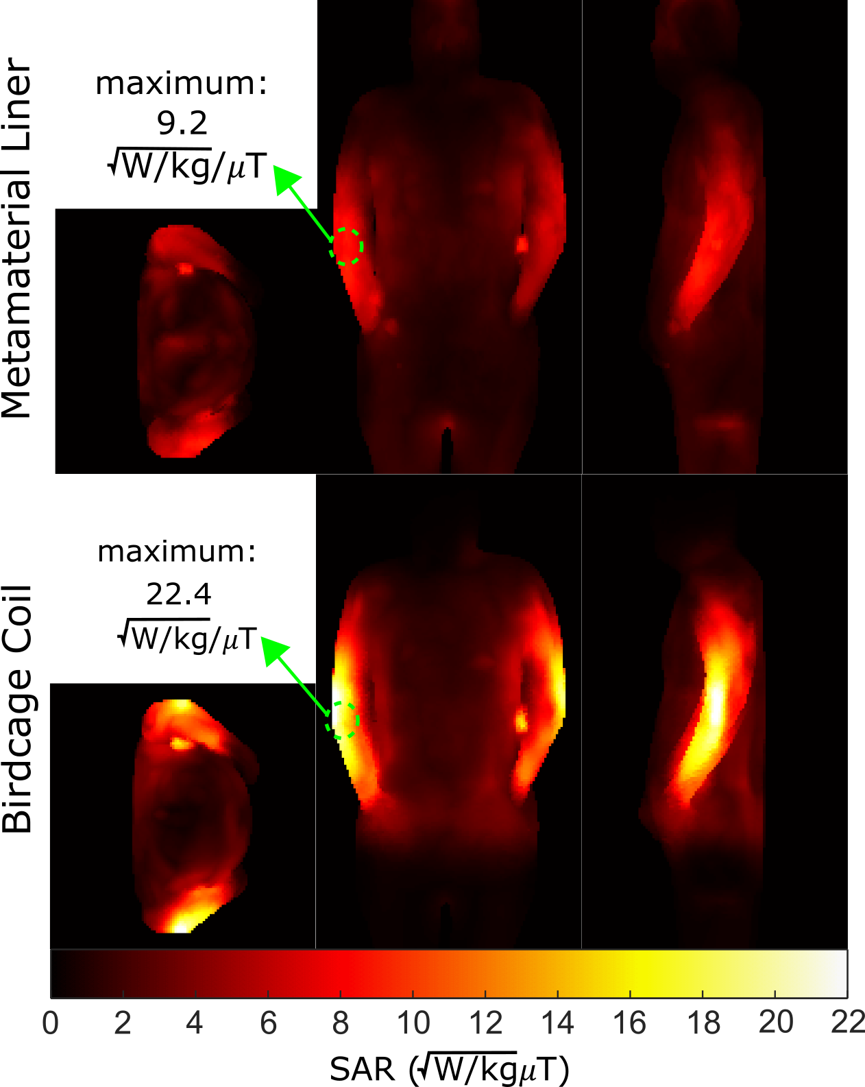
The input impedance and reflection coefficient (quadrature port disconnected) is shown in Figure 3. A excitation for the HE11 mode is required for uniform excitation at isocentre, which is the second longitudinal resonance at 200MHz (the first resonance is the 0th/homogeneous longitudinal mode, where the current phase and magnitude is equal for all rings). The comparison of the fields and transmit efficiency normalized to 1kW input power for the BC coil and metamaterial liner are shown in Figure 4. When unloaded, the mean transmit efficiency inside the outlined region is lower for the metamaterial liner compared to the birdcage coil (4.98 vs. 8.47$$$μT/\sqrt{kW}$$$), and slightly more inhomogeneous (CoV=4.3% vs. 1.8 %). However, when loaded the mean transmit efficiencies are nearly identical (2.84 vs. 2.76$$$μT/\sqrt{kW}$$$), and the metamaterial liner is more homogeneous (CoV=35% vs. 43%). In the maps shown in Figure 5 the SAR is much more evenly distributed along the body for the metamaterial liner compared to birdcage coil. Most importantly, for a normalized mean 1µT excitation the maximum local 10g averaged SAR is significantly lower for the metamaterial liner vs. birdcage coil (9.2 vs. 22.4$$$\sqrt{W/kg}⁄μT$$$).Discussion
In previous designs, the longitudinal coupling between rings was neglected in the analysis of the metamaterial liner6, while here longitudinal wire connections are made explicitly (galvanically) rather than through capacitive or inductive coupling. This new approach and modelling framework allows the rings to be spaced farther apart and increases the spacing of longitudinal resonances. The HEn1 mode spacing and spacing of the longitudinal resonances for the HE11 mode are closely predicted by the network model. Therefore, the model can act as a powerful design tool for the tuning and optimization of the metamaterial liner, without resorting to computationally-expensive full wave simulations. Inclusion of mutual coupling between segments and additional losses may more accurately model the longitudinal resonances of the HE01 mode and absolute values of the input impedance.Conclusion
In realistic loaded conditions, the metamaterial liner offers a more than two-fold reduction in maximum SAR over the birdcage. This highly-desirable property offers enhanced safety margins for high-field whole-body imaging and the opportunity to reduce the limitations imposed on sequences by SAR constraints. Thus, the metamaterial liner is an excellent candidate for high-field volume MR excitation.Acknowledgements
This work was supported by the Alberta Innovates Postdoctoral Fellowship in Health Innovation and the National Sciences and Engineering Research Council of Canada (NSERC) Discovery Grants program.References
1. International Electrotechnical Commission. Particular requirements for the basic safety and essential performance of magnetic resonance equipment for medical diagnosis. 3rd ed. Geneva, Switzerland: IEC 60601–2‐33; 2010.
2. Brunner DO, De Zanche N, Frohlich J, Paska J, Pruessmann KP. Travelling-wave nuclear magnetic resonance. Nature 2009 Feb 19;457(7232):994-998.
3. Zhang B, Sodickson DK, Lattanzi R, Duan Q, Stoeckel B, Wiggins GC. Whole body traveling wave magnetic resonance imaging at high field strength: Homogeneity, efficiency, and energy deposition as compared with traditional excitation mechanisms. Magn Reson Med 2012 Apr;67(4):1183-1193.
4. Alt S, Müller M, Umathum R, Bolz A, Bachert P, Semmler W, et al. Coaxial waveguide MRI. Magn Reson Med 2012 Apr;67(4):1173-1182.
5. Andreychenko A, Bluemink JJ, Raaijmakers AJE, Lagendijk JJW, Luijten PR, van den Berg, C. a. T. Improved RF performance of travelling wave MR with a high permittivity dielectric lining of the bore. Magn Reson Med 2013 Sep;70(3):885-894.
6. Pollock JG, Iyer AK, Pratap D, Anantha Ramakrishna S. A class of circular waveguiding structures containing cylindrically anisotropic metamaterials: Applications from radio frequency/microwave to optical frequencies. J Appl Phys 2016;119(8):083103.
7. Pollock JG, Iyer AK. Below-cutoff propagation in metamaterial-lined circular waveguides. IEEE Transactions on Microwave Theory and Techniques 2013;61(9):3169-3178.
8. Pollock J, De Zanche N, Iyer A. Traveling-wave MRI at lower B0 field strengths using metamaterial liners. Proc. Intl. Soc. Mag. Reson. Med. 2012;20:2792.
9. Hosseini N, Pollock J, Iyer A, De Zanche N. Metamaterial bore liners as high-field body transmit coils: Advantages over standard birdcage coils. Proc. Int. Soc. Mag. Reson. Med 2018;27:4298.
Figures