0182
A 16-channel transmit 96-channel receive head coil for NexGen 7T scanner1Imaging Centre of Excellence, University of Glasgow, Glasgow, United Kingdom, 2MR CoilTech Limited, Glasgow, United Kingdom, 3Max Planck Institute for Human Cognitive and Brain Sciences, Leipzig, Germany, 4Siemens Healthcare GmbH, Erlangen, Germany, 5Faculty of Physics and Earth Sciences, Felix Bloch Institute for Solid State Physics, Leipzig, Germany, 6Helen Wills Neuroscience Institute, University of California, Berkeley, CA, United States
Synopsis
The NexGen 7T scanner has been designed to reach an unprecedented microscale resolution in fMRI studies of the cerebral cortex. A radiofrequency coil setup with a high density receive array is essential to capture the promised benefits. The coil design, which is already constrained by the limited space on the patient table inside the head gradient, must be robust, allow routine scanning and offer a visual field to support fMRI studies. We have developed a compact 16-channel transmit 96-channel receive head coil for the NexGen 7T scanner. In this abstract, we present the coil development and preliminary phantom results.
Introduction
High-density ultra-high field receive arrays are expected to bring significant gains in signal-to-noise-ratio (SNR) and parallel imaging performance1,2. The NexGen-7T scanner is fitted with a head gradient insert and consists of an RF architecture with 16-transmit and 128-receive channels. RF coils for head gradient inserts are constrained by the limited space in the narrow patient table. However, despite the high channel count, the coils must support routine use and offer a visual field to support the fMRI studies. In addition, the transmit and receive arrays must be integrated without influencing the spatial distribution of the transmit field. We present a compact 16-channel transmit 96-channel receive head coil custom-built for the head gradient insert. The coil characterisation and initial phantom measurements are presented here.Methods
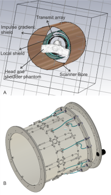
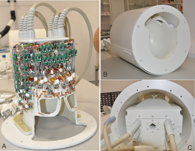
Transmit array: The transmit array consists of 16-elements arranged in two rows3,4. Following on from an earlier work5, the loss mechanisms were investigated and addressed to create an efficient design. The array was constructed on a fiberglass tube of 285mm inner diameter and extended 21cm along the z-direction. The outer tube consisted of a slotted double-layered 7µm shield at a distance of 30mm from the coil. The adjacent elements within the row and between the rows were overlapped and the diagonal elements were inductively decoupled. A view of the simulation setup (CST Studio Suite, Dassault Systems, France) and the transmit array layout is given in figure 1.Receive array: The receive array consisted of 96-elements arranged symmetrically in 6 rows. There are 12 elements in the top row, 18 in the second and 24 in the third row covering from the vertex of the dome to the level of the nose bridge. The other 42 elements covered the remainder of the helmet surface. The size of each receive element was about 30mmx45mm. The two eye loops were larger. A tight fit helmet (175mm along L/R, 215mm along A/P) was chosen to maintain sample loading on the small receive elements. The helmet was shaped using anthropometric data and also had a curvature beneath the skull base to provide a comfortable but tight fit.
The equivalent circuit schematic is as per Ref.3. All circuit boards were miniaturised and a detailed CAD model was created in Solidworks to visualise component placement, cable routing and packaging. A picture of the completed receive array and the final assembly highlighting the visual field achieved despite the limited space is shown in figure 2.
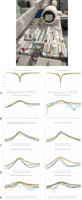
Test setup: An elaborate test setup (figure 3) was required to be able to test this coil in the bench. The test-jigs consisted of: two 8-channel pTx; two 32-channel high-density receive and one 32-channel TIM interfaces.
Tuning, matching, decoupling and preamplifier decoupling of the receive elements were adjusted while the remaining elements were tuned but decoupled using the preamplifiers.
Preliminary tests have been conducted on a 7T Terra scanner (Siemens Healthineers AG, Erlangen, Germany) equipped with 16-transmit channels and 64-received channels. The additional receive channels were actively detuned through the test-jig by biasing through an external power supply.
VOP6: Two body models were simulated in three different positions each. Due to the computational requirements for the 16Tx array, only the worst case from the two models were chosen and a concatenated VOP was generated using the two datasets, after applying a 30% overestimation and a manufacturer recommended measurement error factor.
Results
Transmit array: Coupling between the adjacent elements on each row was less than -16dB and between the two rows was less than -19dB. The diagonal elements were decoupled by more than -20dB. The active detuning of the transmit array was less than -30dB. A plot of the S-parameters characterizing the transmit array with and without the receive array is shown in figure 3. It is important to note that only the tune and match of the transmit elements were adjusted after the receive array was inserted. Clear resonances can be seen for each of the array element despite the presence of the tightly packed receive array. While most of the coupling behavior remained unaltered, influence on two pairs of the top row elements were observed.Receive array: The decoupling between the adjacent elements was in the range of -10 to -12dB. The average preamplifier decoupling of all the 96-receive channels was -21dB and the active detuning was better than -30dB.
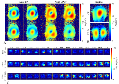
Scanner measurements: Despite the presence of the 96-channel receive array, the combined and single channel B1+ maps (Figure 4) look as expected and no local influence on the spatial distribution can be seen. The CP and the CP2+ maps were acquired by setting the theoretical phase offsets.
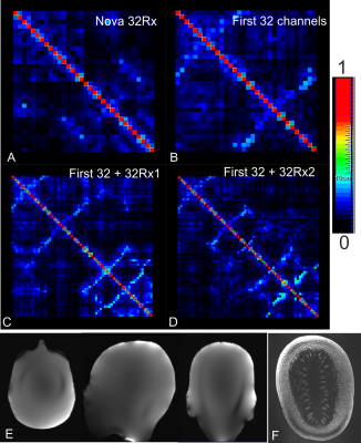
The noise correlation maps (figure 5) demonstrate good decoupling. Most of the nearest coupling coefficients were below 0.3, with only six pairs having values between 0.5 and 0.55.
A first localiser image of the 16Tx96Rx setup from the NextGen-7T and a spaghetti squash 3D FLASH image acquired with 3x5 GRAPPA acceleration with 0.25x0.25x1.5mm resolution are shown in figure 5.
Discussion
Initial measurements demonstrate SNR gain of more than a factor of two closer to coil surface. We expect to further characterise the transmit and receive performance of this coil array in the NexDen-7T scanner.Acknowledgements
1. Dr Ralph Kimmlingen, Siemens Healthcare GmbH, Erlangen, Germany, for helping us with the 16Tx interfacing.
2. Dr An Wu, VA Advanced Imaging Research Center, UCSF, CA, USA for acquiring the 16Tx96Rx images.
References
1. Ugurbil K, Auerbach E, Moeller S, et al. Brain imaging with improved acceleration and SNR at 7 Tesla obtained with 64‐channel receive array. Magn Reson Med. 2019;82:495–509
2. Wiesinger F, Boesiger P, Pruessman KP. Electrodynamics and unlitmate SNR in parallel MR imaging. Magn Reson Med 2004;52:376-390
3. Shajan G, Kozlov M, Hoffmann J, et al. A 16‐channel dual‐row transmit array in combination with a 31‐element receive array for human brain imaging at 9.4 T. Magn Reson Med. 2014;71:870-879
4. Shajan G, Hoffmann J, Adriany G, et al., A 7T head coil with 16-channel dual-row transmit and 32-channel receive array for pTx applications and high SNR. ISMRM 2016 p2132.
5. Kozlov M, Weiskopf N, Moeller H E, et al. Reverse engineering of a 7T 16-channel dual-row transmit array coil. ISMRM 2018 p 4412.
6. Eichfelder G, Gebhardt M. Local Specific Absorption Rate Control for Parallel Transmission by Virtual Observation Points. Magn Reson Med. 2011;66(5):1468-1476.
Figures
