0181
A Patient-Friendly 16ch Tx / 64ch Rx Array for Combined Head and Neck Imaging at 7 Tesla1Institute of Medical Physics and Radiation Protection (IMPS), TH Mittelhessen University of Applied Sciences, Giessen, Germany, 2Siemens Healthcare GmbH, Erlangen, Germany, 3Siemens Medical Solutions USA, Inc., Malvern, PA, United States, 4A.A. Martinos Center for Biomedical Imaging, Dept of Radiology, Massachusetts General Hospital, Harvard Medical School, Boston, MA, United States
Synopsis
A 16chTx / 64chRx head-neck array coil was designed, constructed, and validated at 7T ultra-high field (UHF) MRI. The clinical benefits of UHF neuroimaging were increased by extending coil coverage from the brain region to include the cervical spine. To increase patient compliance, the commonly employed separated transmit and receive coil array functionalities at UFH were combined into one anatomically shaped close-fitting housing which is fully splitable for patient access.
Introduction
There is a growing need for clinical 7T neuroimaging to provide combined head and neck imaging to match the standard of care at 1.5T and 3T for assessment of a variety of neurodegenerative diseases1,2. To address these clinical needs, dedicated RF coils are required that enable transmission and reception for a considerably larger field of view (FOV), than existing 7T brain coils, and improve patient access and workflow by employing more patient-friendly coil designs similar to those used with 1.5T or 3T systems. For example, 7T transmit (Tx) and receive (Rx) coil functionalities at UHF are usually separated into two housing segments, where a close-fitting helmet comprises the receive RF structure, while the Tx structure is housed in a separate sliding tubular former3-5 and pulled over the subject’s head, which often triggers anxiety and discomfort6. In this study, we implemented and validated our initial design considerations for 7T head-neck imaging7 in order to change the commonly employed coil topology for UHF head array coils, by merging the Rx and Tx array structures into one anatomical fitting housing design with a fully splittable design to facilitate entry and exit from the coil.Methods
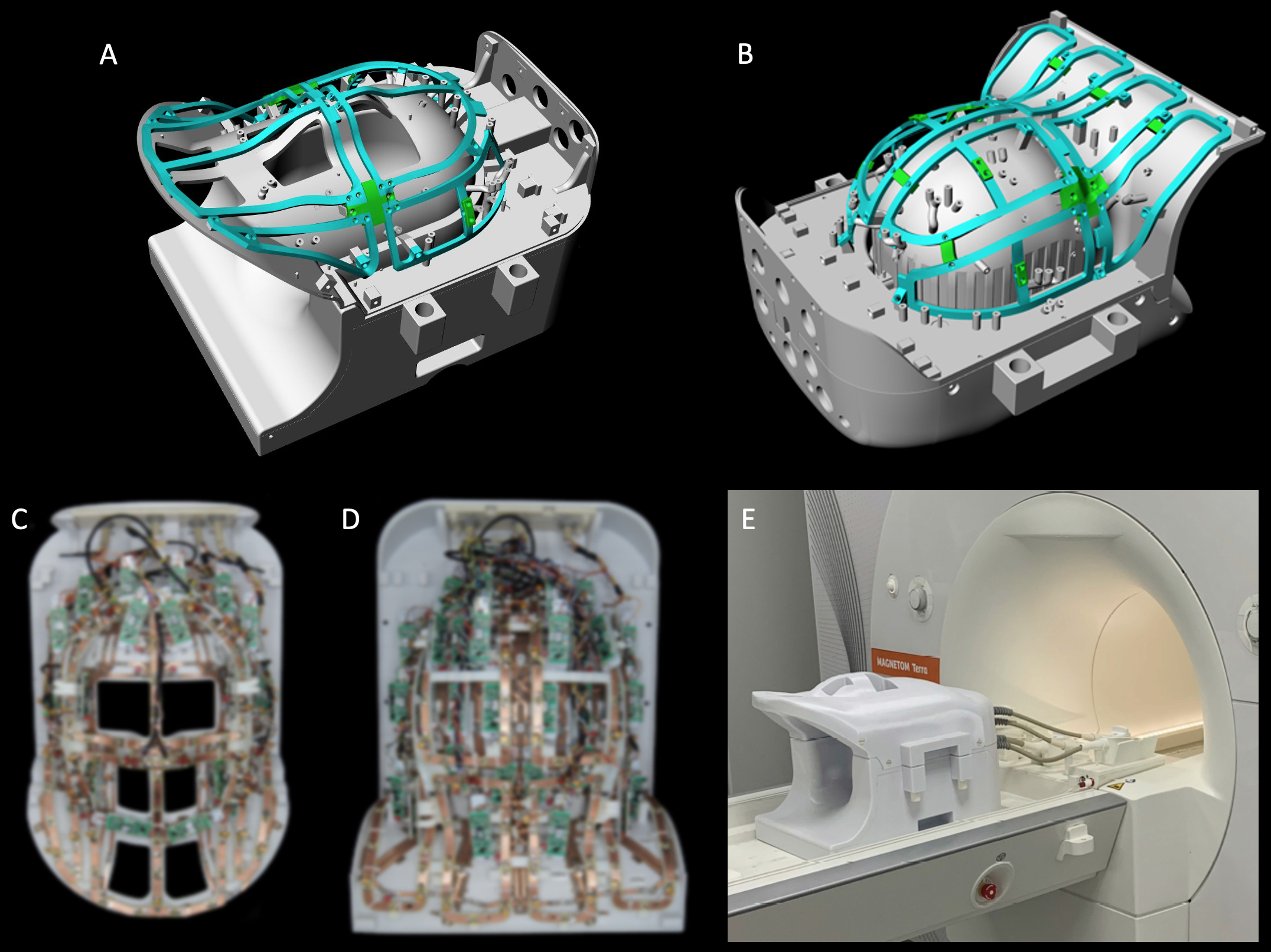
Coil Housing: An anatomically shaped coil former was sized to accommodate the majority of adult heads (95th percentile). The housing was subdivided into an anterior head-neck portion with 24 Rx / 8Tx elements (Fig.1 A), and a large posterior head-neck section with 40 Rx / 8Tx elements (Fig.1 B). All helmet parts were 3D-printed in polycarbonate plastic (Fortus 450, Stratasys, Eden Prairie, USA).Receive Array: 42 close-fitting Rx elements serve the brain and 22 elements were placed along the neck, cervical-spine and face on a surface that nearly matches an existing clinical 3T head-neck coil. All loop elements were made with flexible printed circuit board sheets and geometrically decoupled by critical overlap or shared impedance and further were decoupled with preamplifier decoupling8. The matching network, the active detuning circuitry, and the passive coil detuning network were placed on the preamplifier’s daughterboard.
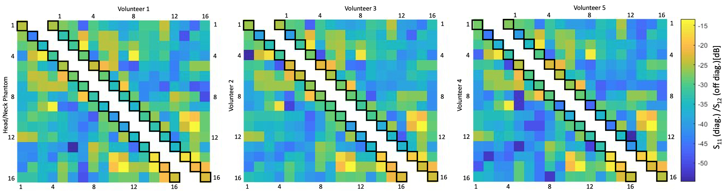
Transmit Array: The loops were mounted on a rail system (Fig. 1 A,B) approximately 1,5-3cm above the Rx element surface. The majority of the Tx elements were isolated with a resonant inductive decoupling method (RID)9. Adjacent Tx loops located over the eyes and mouth were decoupled via shared impedance, to allow larger housing cutouts. Common mode currents on the Tx cables where minimized via bazooka baluns10. Variations in tuning, matching, and decoupling due to different sized loading conditions were bench-tested with five subjects (Fig. 2). For SAR safety purposes and to derive a circularly-polarized B1+ shim set, the Tx array was modelled and simulated (HFSS, ANSYS, Canonsburg, USA).
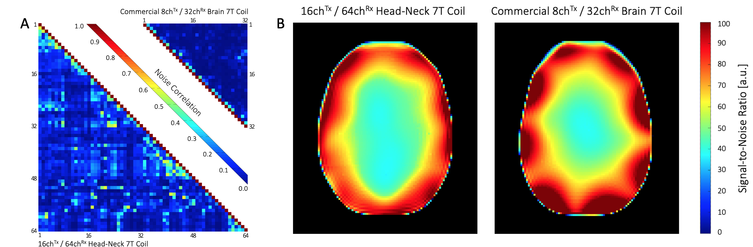
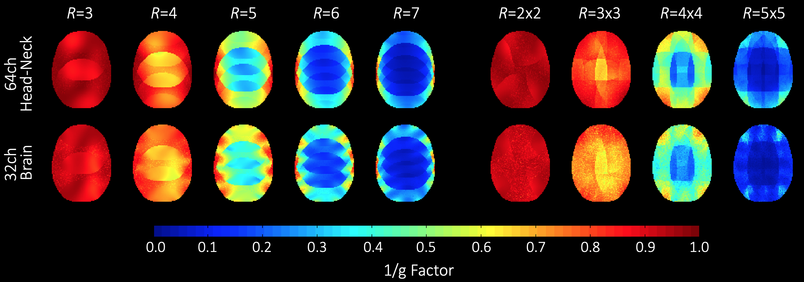
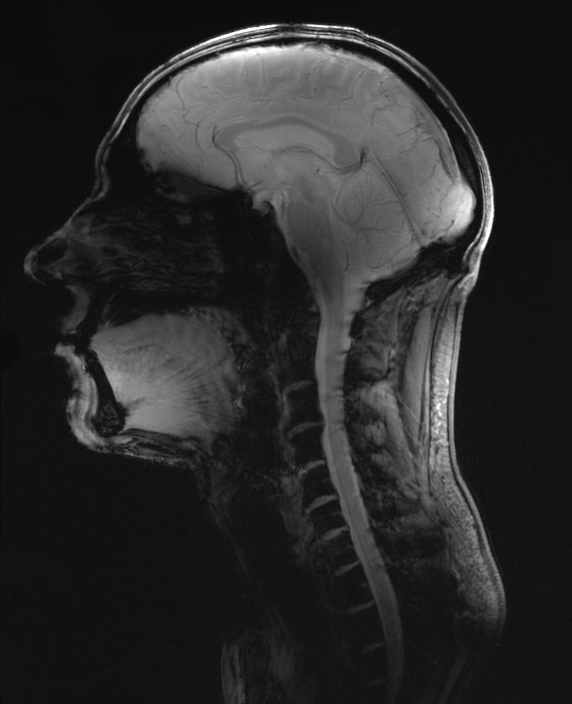
Image acquisition: Data was acquired on a clinical 7T whole-body MRI scanner using a head-shoulder agar phantom, dielectrically tuned to average brain tissue11 and compared to a commercial 8Tx/32Rx (Nova Medical, Wilmington, MA, USA) array. SNR calculations followed the Kellman method12 (Fig. 3). The SNR maps were corrected for B1+ using the measured actual flip angle map, scaled to the applied transmit voltage: SNR90 = SNR/(sin α). Parallel imaging encoding power (Fig. 4) was assessed by computing SENSE g-factors13 for 1D and 2D in-plane accelerations. Finally, the array was tested in vivo with a large FOV (Fig. 5).
Results
Adjacent Tx loop decoupling could be optimized > -13 dB. Decoupling between non-adjacent Tx loop pairs shows an isolation of >25 dB, thus no further decoupling networks where implemented. The Tx coil shows robust tuning/matching and decoupling stability across different subjects (Fig. 2). The Rx array showed decoupling from adjacent elements of -16 dB. The coupling between next-nearest neighbours ranged from -14 dB to -26 dB. Additional isolation of 18 dB was achieved via preamplifier decoupling. Active PIN diode detuning provided >43 dB isolation between the tuned and detuned states. Average noise correlation (Fig. 3A) was measured to be 12.7 % (range 0.1% – 58%). Figure 3B shows the SNR comparison in the brain area. For clinical requirements, the constructed coil is larger sized, thus, the 64ch head-neck array shows slightly lower SNR at the center and the periphery of the brain area when compared to the smaller sized 32ch head array. The encoding capabilities (Fig. 4) from both coils are similar for lower acceleration factors in the brain area, However, the constructed 64ch coil shows slightly better g-factors at higher accelerations.Discussion
Rx and Tx coil structures were independently controllable for the needed adjustments. However, increased noise correlations in the Rx structure indicate additional coupling over the close-fitting Tx coil structure. Initial 7T in vivo large-FOV images show promising results for combined head-neck imaging studies for clinical settings (Fig. 5).Conclusion
A head-neck array coil was designed, constructed, and validated with an emphasized clinical focus for imaging neurological diseases in brain, brainstem and cervical spine at 7T. Our preliminary results show promising potential for increased clinical benefit in UHF neuroimaging by extending coil coverage from the brain region to the cervical spine. Combining the Rx and Tx coil functionalities in a splittable close-fitting housing yielded a more patient-friendly UHF coil design.Acknowledgements
The authors thank Jason Stockmann, Charlotte Sappo, Erica Mason and Azma Mareyam for thoughtful discussions and advice on cable baluns. Furthermore, the authors thank Laleh Golestanirad for advice about simulations in HFSS. The international collaboration was supported by the Fulbright Association and BMBF (German Gov’t funding, ID: IN2016-2-226)References
[1] Bruschi N , Boffa G, Matilde M. Ultra-high-field 7-T MRI in multiple sclerosis and other demyelinating diseases: from pathology to clinical practice Eur Radiol Exp. 2020 Oct 22;4(1):59.
[2] Wright D, Martin S, Pereira EA, Kong Y, Tracey I, Cadoux-Hudson T. High field structural MRI in the management of degenerative cervical myelopathy. Br J Neurosurg. 2018, 24:1-4.
[3] Ledden PJ, Mareyam A, Wang S, an Gelderen P, Duyn J, 32-Channel receive-only SENSE array for brain imaging at 7 T, in: Proceedings of the 15th Annual Meeting of ISMRM, Berlin, 2007, p.242.
[4] Keil B, Triantafyllou C, Hamm M, Wald LL. Design optimization of a 32- channel head coil at 7 T, in: Proceedings of the 18th Annual Meeting of ISMRM, Stockholm, 2010, p.1493.
[5] Shajan G, Kozlov M, Hoffmann J, Turner R, Scheffler K, Pohmann R. A 16-channel dual-row transmit array in combination with a 31-element receive array for human brain imaging at 9.4 T. Magn Reson Med. 2014,71(2):870-9. [6] van Osch, M.J.P. & Webb, A.G. Curr Radiol Rep (2014) 2: 61.
[7] May M, Etzel R, Golestanirad L, Triantafyllou C, Chang YV, Giri S, Wald LL, Keil B, Design Considerations of a 64-Channel Receive / 16-Channel Transmit Coil Array for Head, Neck, and Cervical-Spine Imaging at 7 T, in: Proc. Intl. Soc. Mag. Reson. Med. (ISMRM), 27, Montreal, 2019, p.1519.
[8] Roemer PB, Edelstein WA, Hayes CE, Souza SP, Mueller OM. The NMR phased array, Magn Reson Med (1990) 16: 192–225.
[9] Avdievich N, Pan, J, Hetherington H, (2013). Resonant Inductive Decoupling (RID) for Transceiver Arrays to Compensate for both Reactive and Resistive Components of the Mutual Impedance. NMR Biomed. 2013 Nov;26(11):1547-54.
[10] David M. Peterson Barbara L. Beck G. Randy Duensing Jeffrey R. Fitzsimmons. Common mode signal rejection methods for MRI: Reduction of cable shield currents for high static magnetic field systems. Concepts Magn Reson Part B (Magn Reson Engineering) 2003. Oct 19B: 1–8.
[11] Qi Duan, Jeff H. Duyn, Natalia Gudino, Jacco A. de Zwart, Peter van Gelderen, Daniel K. Sodickson, Ryan Brown. Characterization of a dielectric phantom for high-field magnetic resonance imaging applications. Med Phys. 2014 Oct;41(10):102303
[12] Kellman P, McVeigh ER. Image reconstruction in SNR units: a general method for SNR measurement. Magn Reson Med. 2005 Dec;54(6):1439-47. doi: 10.1002/mrm.20713. Erratum in: Magn Reson Med. 2007 Jul;58(1):211-2. PMID: 16261576
[13] Pruessmann KP, Weiger M, Scheidegger MB, Boesiger P. SENSE: sensitivity encoding for fast MRI. Magn Reson Med. 1999 Nov;42(5):952-62. PMID: 10542355.
Figures