0180
Development of Two Antisymmetric 16-Element Transceiver Coil Arrays for Parallel Transmit Cardiac MRI in Humans at 7T1Chair of Molecular and Cellular Imaging, Comprehensive Heart Failure Center (CHFC), University Hospital Wuerzburg, Wuerzburg, Germany
Synopsis
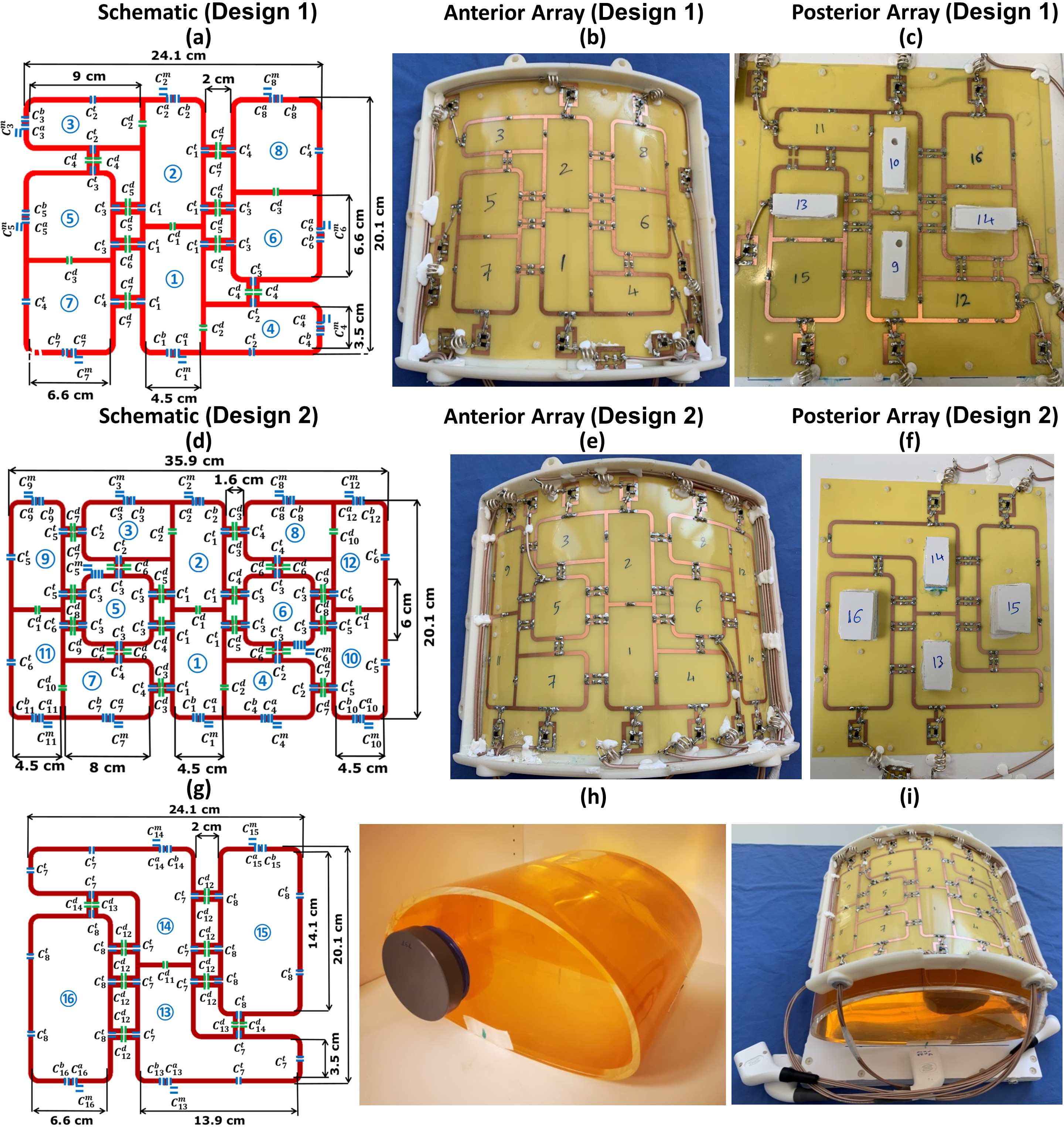
Two antisymmetric, 16-elements, transceiver RF-coil arrays were developed for improved $$${B_1^+}$$$-shimming and parallel imaging for cardiac-MRI in humans at 7T. The first array (Design1) comprised of an 8-loops for both anterior and posterior sections. The second array (Design2) was composed of 12-loops for the anterior section and 4-loops for the posterior section. Electromagnetic-field (EMF) simulations were carried out for both arrays loaded with an elliptical phantom and two human models (Duke and Ella). Static-phase $$${B_1^+}$$$-shimming has been carried out for both arrays with two different optimization cost functions to maximize the transmit-efficiency and weighted combination of $$${B_1^+}$$$-field homogeneity and transmit-efficiency.
Introduction
The application of ultrahigh field (UHF) scanners for cardiovascular MRI at 7T holds significant promise, despite the numerous technical challenges related to $$${B_0}$$$ and $$${B_1^+}$$$-field heterogeneity. Several RF coil array designs have been developed for body imaging at UHF (e.g., using stripline elements1,2, local Tx/Rx loops3–6,dipoles7–9, and combined dipoles/loops10,11). However, still, the development of an optimized pTx-coil array for cMRI at 7T is challenging. The magnitudes and phases of the signal of each individual transmit coil element can be optimized to provide a uniform combined $$${B_1^+}$$$-field distribution within the heart region-of-interest (ROI) (i.e., RF-shimming). The purpose of this study was to develop and compare two antisymmetric, 16-element transceiver RF-coil array designs for cMRI in humans at 7T.Methods
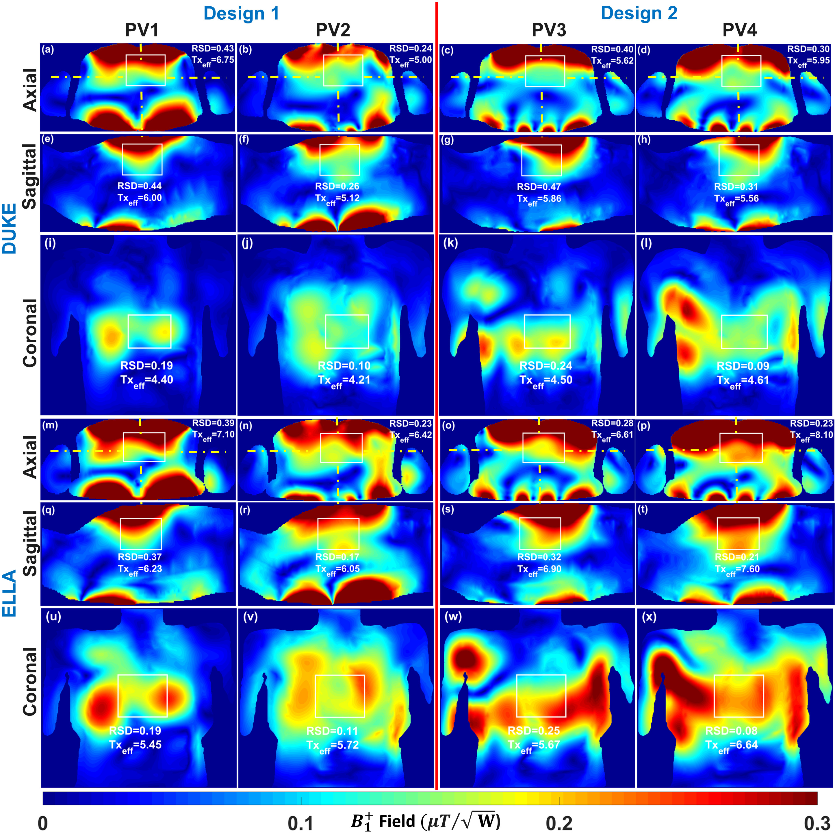
Array design, matching, tuning, and element decoupling were done as described for Design1 in prior publication12. To improve parallel imaging capabilities for slices with double-oblique orientations, the anterior array of Design2 was expanded in comparison to Design1. Additional 4-loops (a new total of 12-elements) were added to the anterior part, aiming to reduce the noise amplification g-factor in the region of the heart for acceleration factors R>4. The total external dimension of Design2 was 20.1cm×35.9cm. The prototypes of Design1 and Design2 with both anterior and posterior sections are shown in Figure 1. For $$${B_1^+}$$$-shimming and 10g averaged SAR calculations, EMF-simulations were carried out using CST-Microwave-Studio (CST-MWS). RF-circuit co-simulation was employed for good matching, tuning, and decoupling at 297.2MHz13. The antisymmetric arrays were loaded with an elliptical-shaped thorax human phantom ($$$\epsilon_{r}$$$=59.3 and $$$\sigma$$$=0.79S/m) and two human voxel models (Duke and Ella). Static phase $$${B_1^+}$$$-shimming has been carried out for both arrays with two different optimization cost functions to maximize $$${B_1^+}$$$-field transmit efficiency and a weighted combination of transmit efficiency and $$${B_1^+}$$$-field homogeneity14. For both designs, optimal phase vectors (PV1 and PV3) were found, targeting maximum transmit efficiency and minimal destructive interference effects within the Duke model. The second set of phase vectors (PV2 and PV4) was found by maximizing a weighted combination of both transmit efficiency and $$${B_1^+}$$$-field homogeneity within the Ella model. For both arrays, the optimal phase vectors obtained in Duke were then applied for Ella and vice versa to ensure the stability of the arrays in phase $$${B_1^+}$$$-shimming under different loading conditions. The relative standard deviation (RSD), transmit efficiency ($$$Tx_{eff}$$$), and SAR efficiency ($$$SAR_{eff}$$$) were used to characterize the Tx performance of both arrays as given by: $$RSD=\frac{std(B_1^+)}{mean(B_1^+)}$$ $$Tx_{eff}=\frac{mean(B_1^+)}{\sqrt{P_{acc}}}$$ $$SAR_{eff}=\frac{mean(B_1^+)}{\sqrt{SAR_{10g,max}}}$$ where, SD($$${B_1^+}$$$) is the standard deviation of the $$${B_1^+}$$$-field and $$$SAR_{10g}$$$ is the maximum achievable 10g averaged SAR with 1W accepted power ($$$P_{acc}$$$). The hardware and imaging performance of the two developed antisymmetric arrays were validated through EMF-simulations and benchtop measurements as well as MR-measurements in a human thorax phantom, and in a 70kg pig cadaver scanned in the first 20min postmortem.Results
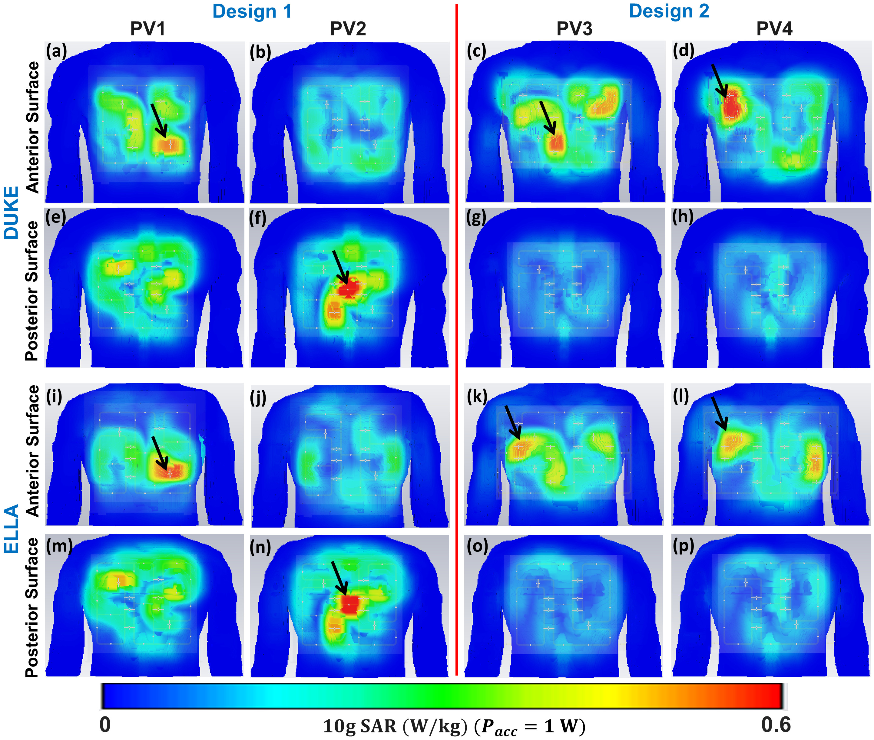
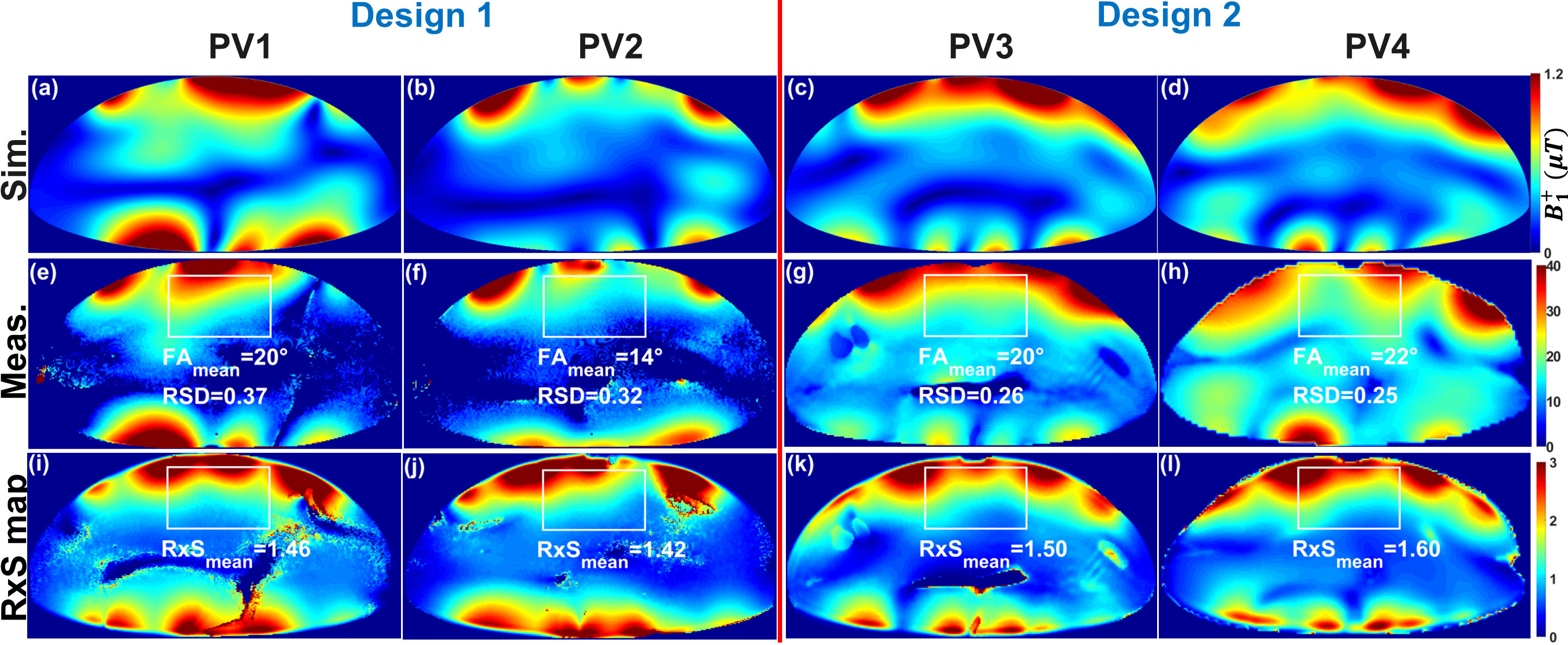
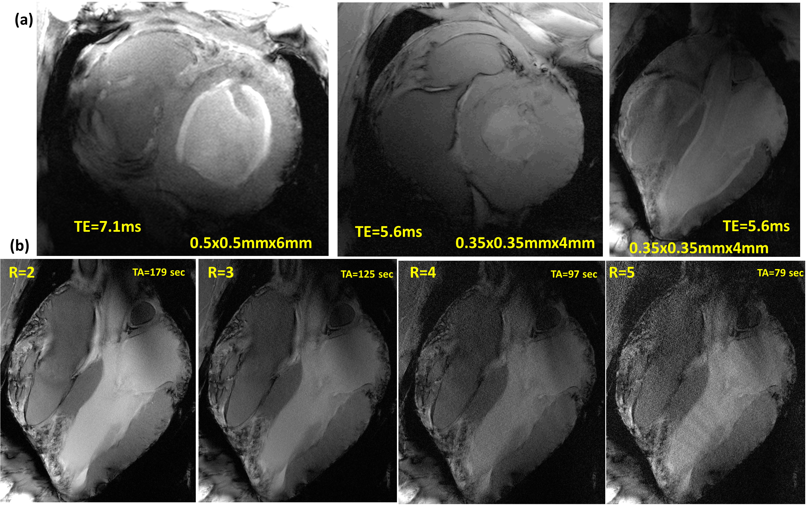
Figure 2 illustrates the $$${B_1^+}$$$-field distribution in central axial, sagittal, and coronal planes for Design1 (PV1 and PV2) and Design2 (PV3 and PV4) within Duke and Ella voxel models. Values of RSD and mean $$$Tx_{eff}$$$ were computed in the selected ROIs of the heart and written on the top of each image in all planes. With PV1, $$$Tx_{eff}$$$ was improved by about 35% compared to PV2. With PV2 (the weighted combination of $$${B_1^+}$$$-field homogeneity and transmit efficiency), the RSD was decreased by 44% in Duke and 41% in Ella. Both $$$Tx_{eff}$$$ and $$$SAR_{eff}$$$ were improved with PV1 compared to PV2. However, for PV2, the $$${B_1^+}$$$-field homogeneity is superior to that observed for PV1. In particular, the coronal and sagittal views for both Duke and Ella revealed better penetration and coverage of the heart compared to PV1. Design2, with PV4, has the best $$$Tx_{eff}$$$=8.10$$$\mu{T}\sqrt{kW}$$$ and $$$SAR_{eff}$$$=0.36$$$\mu{T}\sqrt{W/kg}$$$ compared to Design1. Figure 3 illustrates the local $$$SAR_{10g}$$$ distribution for both designs within Duke and Ella voxel models. According to IEC regulations with a safety margin of factor 2, the maximum local $$$SAR_{10g}$$$ for both arrays were below 14W/kg (10s averaging time). Figure 4 demonstrates the simulated central transversal $$${B_1^+}$$$-field and the measured FA-maps within the human thorax phantom acquired using both designs. Values of RSD were 0.37, 0.32, 0.26, and 0.25 for PV1, PV2, PV3, and PV4, for Design1 and Design2, respectively. Design2 with PV3 and PV4 improved the FA-homogeneity by about 48% compared to Design1. Design2 showed increased $$${B_1^+}$$$-field penetration at ~10cm depth with better Tx-efficiency compared to Design1. Figure 5 demonstrates the ultra-high resolution (0.35×0.35×4mm3) T2* weighted short-axis (SA) and long-axis (LA) images. The used $$${B_1^+}$$$-shimming settings (PV3) provide enough SNR to visualize both the lateral and posterior left ventricular wall (SA-view) with fine structural details. The LA-view demonstrates homogeneous $$${B_1^+}$$$-field within the whole heart region with no apparent destructive interferences.Discussion
The extension of an 8-element anterior array (Design1) to a denser 12-element anterior array (Design2) provided additional capabilities for $$${B_1^+}$$$-shimming, parallel imaging, and improved $$${B_1^+}$$$-penetration [Figures 2&4]. With Design2, parallel imaging with up to R=6 was possible in the L−R direction, whereas for Design1, acceleration of R>4 was practically not feasible.Conclusion
The antisymmetric array design with increased anterior surface and number of allocated elements demonstrated a significant advancement in $$${B_1^+}$$$-shimming capability, parallel imaging, and enabling acceleration up to R=6.Acknowledgements
This project is funded by the German Ministry of Education and Research (BMBF) with grant # 01EO1004 & 01EO1504. We thank Maya Bille for the help in the animal experiments.References
- C.J. Snyder et al., Initial results of cardiac imaging at 7 Tesla, Magn. Reson. Med. 61 (3) (2009) 517–524.
- J.T. Vaughan et al., Whole-body imaging at 7T: preliminary results, Magn. Reson. Med. 61 (1) (2009) 244–248.
- A. Graessl et al., Modular 32-channel transceiver coil array for cardiac MRI at 7.0T, Magn. Reson. Med. 72 (1) (2014) 276–290.
- M.A. Dieringer et al., Design and application of a four-channel transmit/receive surface coil for functional cardiac imaging at 7T, J. Magn. Reson. Imag. 33 (3)(2011) 736–741.
- A. Gräßl et al., Design, evaluation and application of an eight channel transmit/receive coil array for cardiac MRI at 7.0T, Eur. J. Radiol. 82 (5) (2013) 752–759.
- C. Thalhammer et al., Two-dimensional sixteen channel transmit/receive coil array for cardiac MRI at 7.0 T: design, evaluation, and application, J. Magn Reson Imag. 36 (4) (2012) 847–857.
- C. Oezerdem et al., 16-channel bow tie antenna transceiver array for cardiac MR at 7.0 tesla, Magn. Reson. Med. 75 (6) (2016) 2553–2565.
- A.J.E. Raaijmakers, P.R. Luijten, C.A. van Den Berg, Dipole antennas for ultrahigh-field body imaging: a comparison with loop coils, NMR Biomed. 29 (9) (2016) 1122–1130.
- M.A. Ertürk et al., Toward imaging the body at 10.5 tesla, Magn. Reson. Med. 77 (1) (2017) 434–443.
- M.A. Ertürk, A.J. Raaijmakers, G. Adriany, K. Ug˘urbil, G.J. Metzger, A 16-channel combined loop-dipole transceiver array for 7 Tesla body MRI, Magn. Reson. Med. 77 (2) (2017) 884–894.
- B.R. Steensma et al., An 8-channel Tx/Rx dipole array combined with 16 Rx loops for high-resolution functional cardiac imaging at 7 T, Magn Reson Mater Phy 31 (1) (2018) 7–18.
- I. A. Elabyad et al., Development and RF Shimming of an 8Tx/16Rx Antisymmetric Transceiver Coil Array for Parallel Transmit Cardiac MRI in Humans at 7T. Proceedings of the 28th Annual Meeting of ISMRM (Virtual meeting, 2020).
- M. Kozlov, R. Turner, Fast MRI coil analysis based on 3-D electromagnetic and RF circuit co-simulation, J. Magn Reson 200 (1) (2009) 147–152.
- Elabyad IA, Terekhov M, Lohr D, Stefanescu MR, Baltes S, Schreiber LM. A Novel Mono-surface Antisymmetric 8Tx/16Rx Coil Array for Parallel Transmit Cardiac MRI in Pigs at 7T. Scientific Reports. 2020;10(1):3117.
Figures