0177
A 128-channel receive array for 10.5T human head imaging1Center for Magnetic Resonance Research, University of Minnesota, Minneapolis, MN, United States
Synopsis
A 128-channel receive array has been designed and prototyped for human head imaging at 10.5T. The coil employs miniaturized electronics and flexible PCB laminates for loop conductors. Bench measurements and MR experimental results for an 8-channel cluster of loops are presented which show low coil coupling and good stability during echo-planar imaging. Electromagnetic simulations will provide an estimate for the SNR gain that can be expected from this 128-channel receive array over a 64-channel receive array tuned to the same frequency. This simulation estimate will be verified with experimental results which will include intrinsic SNR and g-factor maps.
Introduction
High channel count MRI receive arrays offer benefits both for high SNR and particularly for acceleration [1]. There is, however a coil size related optimal number of channels for a given field strength and application. For example, Schmitt et al. [2] and Wiggins et al. [3] showed that for non-peripheral regions a 128 body array and a 96-channel coil at 3T, coil-noise rather than sample-noise dominated while Keil et al. [4] for 64 channel at 3T demonstrated significant SNR boost. Even more promising results have been shown recently with 64-channel coils at 7T [5,6] which show clear increases to SNR and parallel imaging performance over a 32-channel reference coil. As predicted by Hendriks et al. [7] with their experimental work to estimate performance of a 7T 256-channel coil the primary benefit of higher channel counts is peripheral SNR and g-factor while central SNR tends to remain the same. It has been shown that higher field (e.g. 9.4T, 10.5T) offers a global gain to SNR [8]. Based on these results and predictions it is expected that 10.5T supports 128-channel receive arrays for human head imaging.Electromagnetic simulations will provide an estimate for the SNR gain that can be expected from this 128-channel receive array over a 64-channel receive array tuned to the same frequency. This simulation estimate will be verified experimentally and will include intrinsic SNR and g-factor data.
Methods
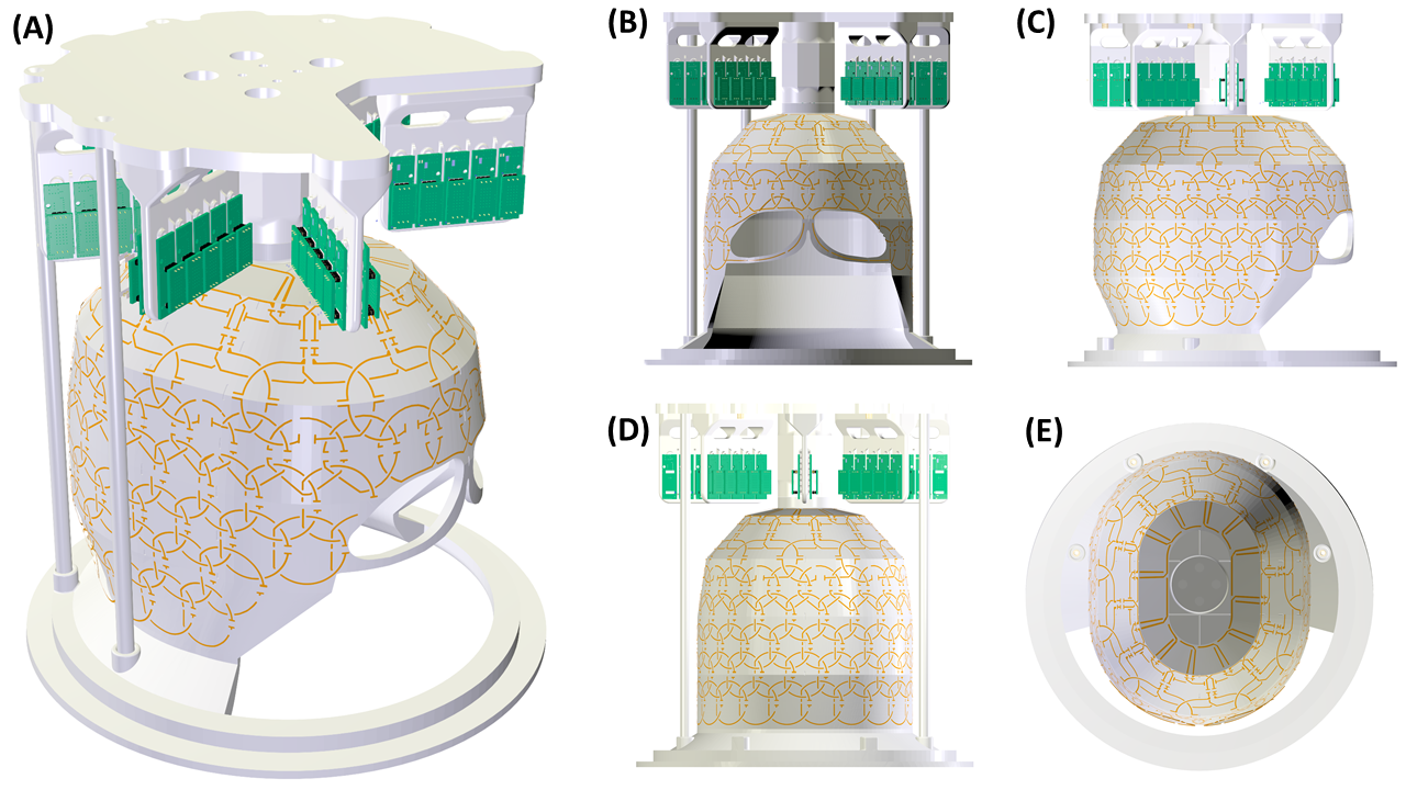
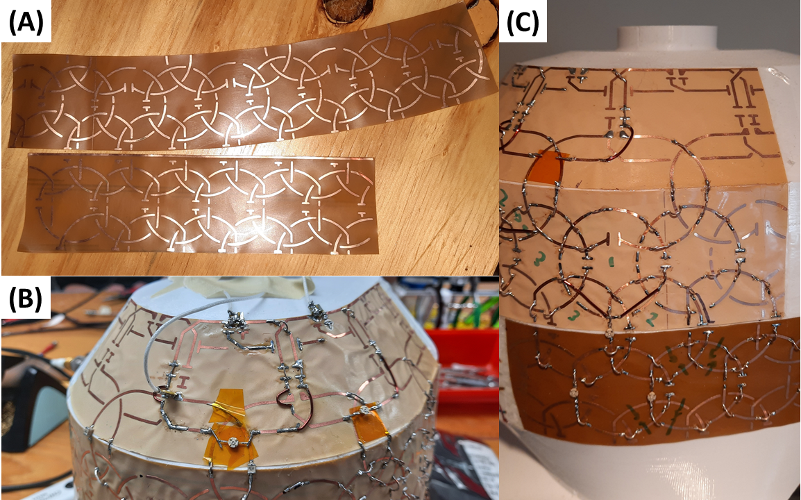
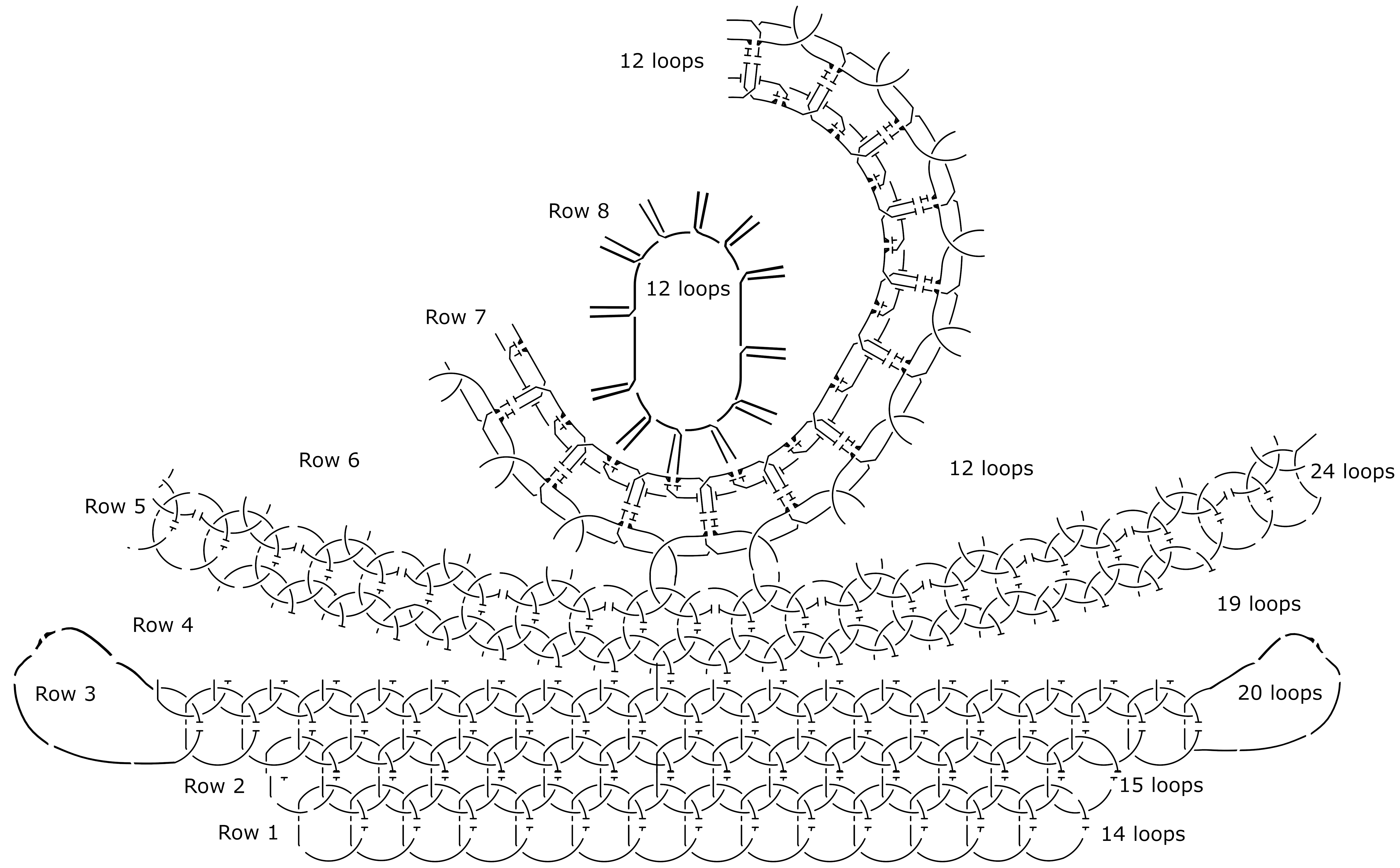
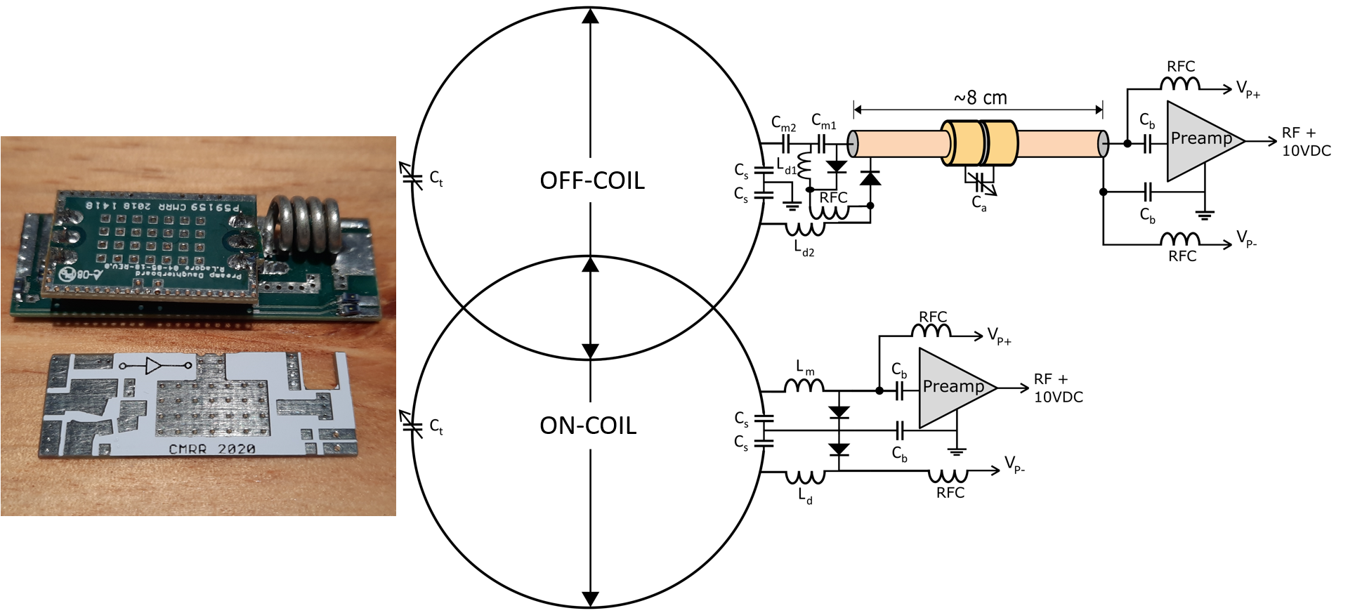
All coil formers are composed of PETG and 3D printed in-house using FDM (Fusion3 F410, Greensboro, NC, USA).The transmit array is composed of 2x8 square loops 10x10 cm2 in size [9] on a 27 cm ID cylindrical former. The receive array former was designed (in SolidWorks, Dassault Systemes, FR) to be a conformal helmet accommodating human head sizes up to the 99%ile. The shape of the helmet is based on a 32-channel 10.5T receive array [10]. The surface of the helmet has been modified, however, to be composed almost entirely of zero gaussian curvature (K=k1k2=0) surfaces. This enables 2D drawings to be wrapped onto the 3D surface without warping (Figure 1). This allows loop conductors to be etched into a flexible PCB laminate (AC354500R and FR9110R, DuPont Pyralux, Wilmington, DE) which can then be wrapped onto the helmet without wrinkling or deformation (Figure 2). The loop layout (Figure 3) is composed of 8 rows of 14-15-20-19-24-12-12-12 loops (top-to-bottom). The bottom row and eye loops are constructed of 18 AWG (1.0 mm diameter) wire loops. The remaining loops are composed of 1 mm wide PCB traces etched into 35 µm thick copper. Both on-coil and off-coil preamps are used in this coil (Figure 4). There is adequate space to mount half of the preamps above the helmet on mounting brackets. These off-coil preamp boards have integrated output traps and the PCB is 40 mm x 14 mm. The other half of the preamps are located on-coil both to maximize SNR potential and avoid overcrowding the mounting brackets. The on-coil preamp PCB is 31 mm x 11 mm and relies on an output trap attached to the coaxial feed cable. The preamp used is the WMA447D (WanTcom, Minneapolis, USA) with specs as follows:
|Zin| = 1.5 Ω
NF = 0.5 dB
Gi = 28 dB
P0.1dB = 1.0 dB
Pin max = 40 dBm @ 6% duty cycle
Loop feed coaxial cable is composed of UT-47C-LL which is 1 mm diameter low-loss, semi-rigid coaxial cable. Cabling is routed along the centerline of transmit loops to minimize transmit-to-receive interaction. Cables are populated with coaxial cable traps both to attenuate common-mode currents and reduce induced currents from the transmitter.
Results
A cluster of eight channels have been tested on the bench and at the magnet to ensure that loops and electronics perform well. Unloaded Q-factor was measured on the bench with a decoupled B-field probe.Wire loops QU = 300
Printed circuit loops QU = 250
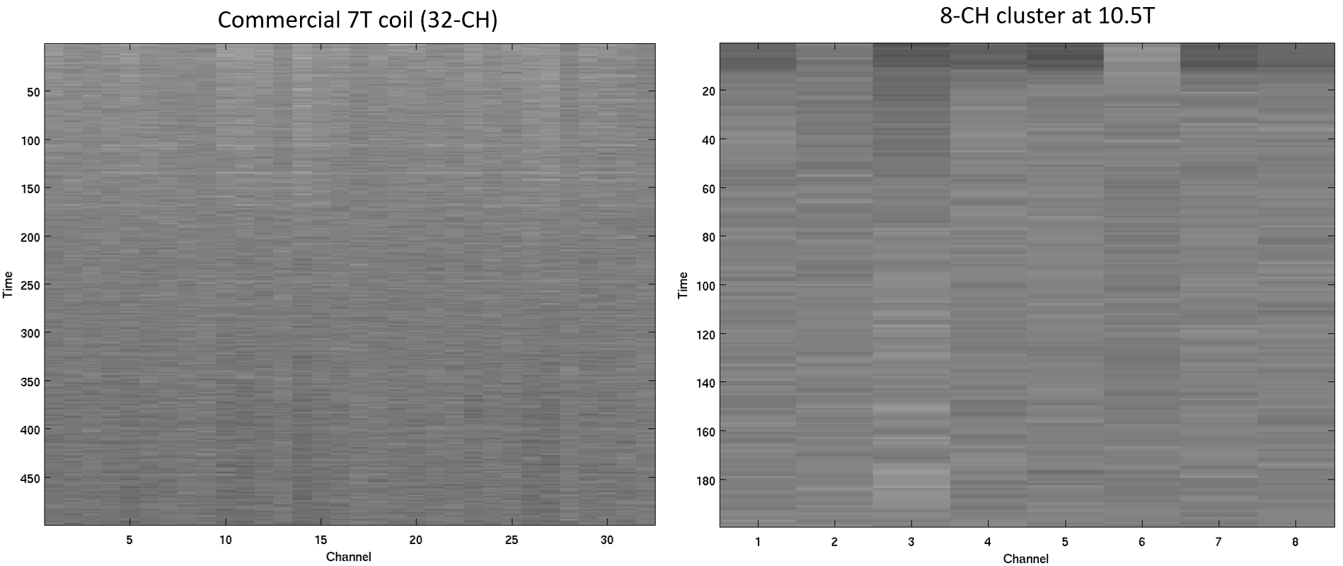
In both cases, QL = ~30. Q-ratios (QU/QL) > 7 and the coil is sample-noise dominated. Typical nearest-neighbor (NN) coupling is -13.1 dB while in-row next nearest neighbor (NNN) coupling (which does not benefit from geometric (overlap) decoupling) is -11.4 dB. Cross-row NNNs are closer together than in-row, and coupling is as high as -7.1 dB. Preamp decoupling decreases coupling to -32 dB for NNs and -17 dB for NNNs. Stability was quantified via temporal SNR plots during 200 EPI measurements. The stability of this loop cluster is comparable to a reference commercial 7T coil (Figure 5).
Discussion
The lower unloaded Q-factor is an obvious drawback of the printed circuit loops when compared to wire loops, however the advantages are significant:- Dramatically reduced labor
- Better symmetry and geometry
- Better reproducibility
Acknowledgements
This research was funded by NIH U01 EB025144, BTRC P41 EB027061, P30 NS076408, NIH S10 RR029672, and NIH R34AG055178 grants.References
[1] Wiesinger, F., Van de Moortele, P. F., Adriany, G., De Zanche, N., Ugurbil, K. & Pruessmann, K. P., 2006. Potential and feasibility of parallel MRI at high field. NMR Biomed 19, 368-378. Epub Date: 2006/05/18 PMID: 16705638,
[2] Schmitt, M., Potthast, A., Sosnovik, D. E., Polimeni, J. R., Wiggins, G. C., Triantafyllou, C. & Wald, L. L., 2008. A 128-channel receive-only cardiac coil for highly accelerated cardiac MRI at 3 Tesla. Magn Reson Med 59, 1431-1439. Epub Date: 2008/05/29 PMID: 18506789 PMCID: PMC2548273
[3] Wiggins, G. C., Polimeni, J. R., Potthast, A., Schmitt, M., Alagappan, V. & Wald, L. L., 2009. 96-Channel receive-only head coil for 3 Tesla: design optimization and evaluation. Magn Reson Med 62, 754-762PMID: 19623621,
[4] Keil, B., Blau, J. N., Biber, S., Hoecht, P., Tountcheva, V., Setsompop, K., Triantafyllou, C. & Wald, L. L., 2013. A 64-channel 3T array coil for accelerated brain MRI. Magn Reson Med 70, 248-258 PMID: 22851312 PMCID: PMC3538896
[5] Uğurbil, K., Auerbach, E., Moeller, S., Grant, A., Wu, X., Van de Moortele, P. F., Olman, C., DelaBarre, L., Schillak, S., Radder, J., Lagore, R. & Adriany, G., 2019. Brain imaging with improved acceleration and SNR at 7 Tesla obtained with 64-channel receive array. Magn Reson Med 82, 495-509. Epub Date: 2019/02/26 PMID: 30803023 PMCID: PMC6491243
[6] Mareyam, A., Kirsch, J.E., Chang, Y., Madan, G., Wald, L.L., 2020. A 64-Channel 7T array coil for accelerated brain MRI. ISMRM 2020, 0764.
[7] Hendriks, A. D., Luijten, P. R., Klomp, D. W. J. & Petridou, N., 2019. Potential acceleration performance of a 256-channel whole-brain receive array at 7 T. Magn Reson Med 81, 1659-1670. Epub Date: 2018/09/27 PMID: 30257049 PMCID: PMC6585755
[8] Pohmann, R., Speck, O. & Scheffler, K., 2016. Signal-to-noise ratio and MR tissue parameters in human brain imaging at 3, 7, and 9.4 tesla using current receive coil arrays. Magn Reson Med 75, 801-809. Epub Date: 2015/03/31 PMID: 25820458,
[9] Adriany, G., Radder, J., Tavaf, N., Lagore, R., Jungst, S., Woo, M.K., Grant, A., Eryaman, Y., Zhang, B., Gundamony, S., Lattanzi, R., Ugurbil, K., Van de Moortele, P-F, 2019. Evaluation of a 16-Channel Transmitter for Head Imaging at 10.5T. 2019 International Conference on Electromagnetics in Advanced Applications (ICEAA), Granada, Spain. pp. 1171-1174, doi:10.1109/ICEAA.2019.8879131.
[10] Tavaf, N., Lagore, R.L., Jungst, S., Gunamony, S., Radder, J., Grant, A., Moeller, S., Auerbach, E., Ugurbil, K., Adriany, G., Van de Moortele, P-F, 2020. Developing High Channel Count Receive Arrays for Human Brain Imaging at 10.5T. ISMRM 2020, 4026.
Figures