0176
A 128-Channel head coil array for Cortical Imaging at 7 Tesla1Department of Radiology, A.A. Martinos Center for Biomedical Imaging, Massachusetts General Hospital, Harvard Medical School, Charlestown, MA, United States, 2High Field MR Center, Center for Medical Physics and Biomedical Engineering, Medical University Vienna, Vienna, Austria, 3Department of Life Science Engineering, Institute of Medical Physics and Radiation Protection, Mittelhessen University of Applied Science, Giessen, Germany, 4Helen Wills Neuroscience Institute, University of California, Berkeley, Berkeley, CA, United States
Synopsis
A 128-channel receive array for cortical brain imaging at 7T was simulated and constructed. The tight-fitting brain-only coil was designed for use with a recently constructed head gradient system (Gmax = 200 mT/m and Smax = 900mT/m/s) for use with either a single channel birdcage Tx or a 24-channel pTx coil. The goal was to maximize cortical SNR and achieve the high acceleration needed for single-shot EPI based fMRI at high sub-millimeter isotropic resolution.
Introduction
Human fMRI studies with single shot acquisitions have recently broken the 1 mm isotropic resolution barrier, but resolutions surpassing 0.5 mm are needed to approach the biological limits of fMRI resolution [1] [2] and delineate laminar and columnar functional organization. Although zoomed imaging techniques [3] can help with the spatial encoding [4] [5] [6], larger regions are needed for a more complete view of cortical architecture, requiring higher SNR and parallel imaging performance than current receive coils (Rx) can achieve. As part of the MR Corticography (MRCoG) NIH Brain Initiative project (U01EB025162), which is exploring the limits of cortical imaging, a customized tight fitting 128-channel receive head-only coil array is designed, simulated and constructed.Methods
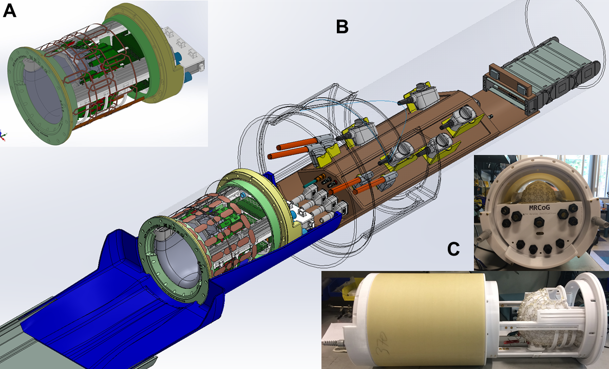
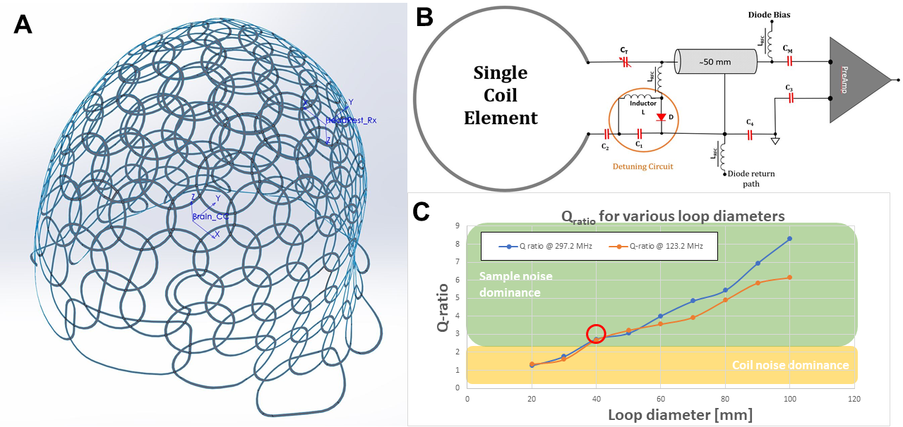
Figure 1 shows the tight space constraints within the 37 cm space provided on the table top of the 44 cm dia. head gradient (with 40 cm dia. clear-bore) of the upgraded Siemens MAGNETOM Terra system (Siemens Healthineers, Erlangen, Germany). Space constraints made it necessary to minimize electronics and their interaction with each other to not only fit the receive and transmit components but also house future integration of B0 shim components. The configuration is shown in Fig.1. Figure 1C shows the 3D printed (Fortus F360mc, Stratasys, MN, USA) non-splitable helmet former (ABC-PC), with 128 attached loops of 44 mm diameter, which fits 75% of the male population and almost 100% of the female population.Each loop (Fig. 3B), made of 16 AWG tin-plated wire, is tuned to 297.2 MHz and impedance matched under loaded condition, to minimize the noise figure of the Siemens 7T preamplifiers. All bench measured values were acquired without an RF fuse in the loop, using a loosely coupled double probe (S21: -75dB) in 20 mm distance to the loop and with a 5 mm foam spacer between the sample (loading phantom: 0.2 S/m DC, with 0.2 ml/l Gd) and the loop. Adjacent elements were inductively decoupled using critical overlap [7] [8]. Coupling between next-nearest neighbours is addressed utilizing preamplifier (PA) decoupling, by transforming the low impedance of the PA to an open circuit in the loop using a 50 mm long coaxial cable and a series capacitor of 8 pF.
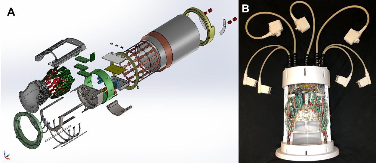
The Tx coil consisted of a 1-ch detune-able band-pass Tx birdcage coil with 16-rungs of length 280 mm length, mounted on the inside of a 320 mm fiberglass tube (330mm length) within a slotted shield with a 269 mm diameter (Fig. 1B and 2A).
Coil simulations were carried out in MARIE (Magnetic Resonance Integral Equation Suite) [9] with a unit driving coil in each loop laid out to accurately match the constructed loop configuration (Fig. 3A). The simulated performance was compared to a 32-ch (loop dia. 88 mm) and 64-ch (loop dia. 63 mm) head coil [10] [11], with each loop layout positioned on the same helmet former. The simulation in MARIE used a homogeneous head phantom (average brain: ε=52, σ=0.55 S/m). SNR maps are computed according to Roemer et al. [8] and included coil copper losses, estimated from measured Q-ratio data.
Results
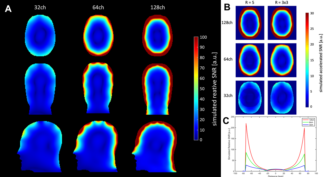
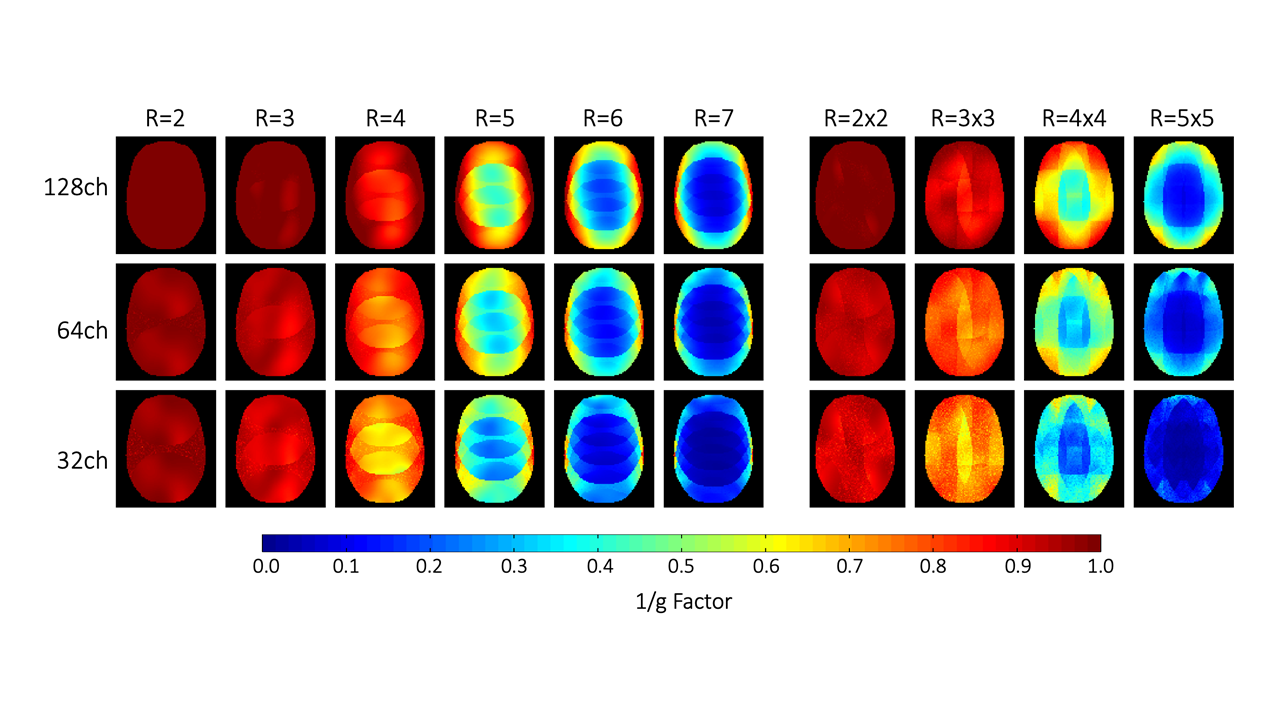
The 44mm dia. loops show a Qloaded of 43.2 and Qunloaded of 189 (Q-ratio=4.38), and with six surrounding elements the Qratio drops to 2.73 (Fig. 3C). Inductive decoupling between two loops is -17 dB, and preamplifier decoupling is about -30 dB. In average for the whole array, the values go down to -12 dB for the inductive decoupling and -15 dB for the preamplifier decoupling.Unaccelerated SNR (Fig. 4A) in the cortical area is predicted to have a substantial increase going from 32- to 128-channels and a 2.3-fold increase from 64- to 128 receive channels with no gain at the center of the head (Fig. 4C). 2D and 1D accelerated SNR with R=3x3 and R=5 for the 128-channel array demonstrate the benefits for accelerated imaging of the cortex, compared to the 64- or 32-channel array (Fig. 4B and 5). At acceleration rate R=4, the maximum 1/g-factor for the 128-channel array is about 72 % of that of the 32-channel array. For R=3x3 in 2D acceleration, the maximum g-factor was 88 % of the 32-channel array.
Discussion and Conclusion
The simulated and presented 128-ch array (Fig. 2B) is expected to increase the sensitivity in cortical regions by providing SNR substantially higher than with a 64-channel array through a combination of intrinsic SNR and g-factor improvements. The 128-channel array will be tested in vivo following the completion of the system upgrade to 128 Rx channels for 7T.Acknowledgements
Research reported in this publication was supported by the NIH BRAIN Initiative, the National Institute of Biomedical Imaging and Bioengineering, under award numbers U01EB025162. The content is solely the responsibility of the authors and does not necessarily represent the official views of the National Institutes of Health.
References
[1] A. J. Poplawsky, M. Fukuda, B. Kang, J. H. Kim, M. Suh and S.-G. Kim, "Dominance of layer-specific microvessel dilation in contrast-enhanced high-resolution fMRI: Comparison between hemodynamic spread and vascular architecture with CLARITY," NeuroImage, no. 197, pp. 657-667, 2019.
[2] J. R. Polimeni and L. L. Wald, "Magnetic Resonance Imaging technology - bridging the gap between non-invasive human imaging and optical microscopy," Current Opinion in Neurobiology, no. 50, pp. 250-260, 2018.
[3] D. A. Feinberg, J. C. Hoenninger, L. E. Crooks, L. Kaufman, J. C. Watts and M. Arakawa, "Inner volume MR imaging: technical concepts and their application," Radiology, vol. 156, no. 3, 1985.
[4] K. Setsompop, D. A. Feinberg and J. R. Polimeni, "Rapid brain MRI acquisition techniques at ultra-high fields," NMR in Biomedicine, no. 29(9), pp. 1198-1221, 2016.
[5] L. Huber, D. Ivanov, S. N. Krieger, M. N. Streicher, T. Mildner, B. A. Poser, H. E. Moeller and R. Turner, "Slab selective, BOLD-corrected VASO at 7 Tesla provides measures of cerebral blood volume reacitivity with high signal-to-noise ratio," Magn. Reson. in Med., no. 72(1), pp. 137-148, 2014.
[6] R. M. Heidemann, D. Ivanov, R. Trampel, F. Fasano, H. Meyer, J. Pfeuffer and Turner R., "Isotropic submilimetere fMRI in the human brain at 7T: combining reduced field-of-view imaging and partially parallel acquisition," Magn. Reson. in Med., no. 68(5), pp. 1506-1516, 2012.
[7] B. Keil and L. L. Wald, "Massively parallel MRI detector arrays," Journal of Magnetic Resonance, no. 229, pp. 75-89, April 2013.
[8] P. B. Roemer, W. A. Edelstein, C. E. Hayes, S. P. Souza and O. M. Mueller, "The NMR phased array," Magnetic Resonance in Medicine, vol. 16, pp. 192-225, 1990.
[9] J. F. Villena, A. G. Polimeridis, A. Hochman, Y. Eryaman, E. Adalsteinsson, L. L. Wald, J. K. White and L. Daniel, "Fast electromagnetic analysis of MRI transmit RF coilsbased on accelerated integral equation methods," IEEE Trans. Biomed. Eng., 2016.
[10] A. Mareyam, J. Cohen-Adad, J. N. Blau, J. R. Polimeni, B. Keil and L. L. Wald, "A 32 Channel receive-only 3T array optimized for brain and cervical spine imaging," in Proce. Intl. Soc. Mag. reson. Med. 18, Stockholm, 2010.
[11] B. Keil, J. N. Blau, S. Biber, P. Hoecht, V. Tountcheva, K. Setsompop, C. Triantafyllou and L. L. Wald, "A 64-channel 3T array coil for accelerated brain MRI," Magnetic Resonance in Medicine, vol. 70, pp. 248-258, 2012.
Figures