0175
Coil Design Impacts Image Encoding: Optimized 64-Channel Array Configurations for Diffusion-Weighted Imaging in 3T Cardiac MRI1Institute of Medical Physics and Radiation Protection, Department of Life Science Engineering, TH Mittelhessen University of Applied Sciences, Giessen, Germany, 2Philipps-University of Marburg, Department of Diagnostic and Interventional Radiology, Marburg, Germany, 3Harvard Medical School, Massachusetts General Hospital, Department of Radiology, A.A. Martinos Center for Biomedical Imaging, Boston, MA, United States, 4Princeton University, Princeton, NJ, United States
Synopsis
To determine the optimum configuration of a 64-channel array coil for highly accelerated in vivo cardiac diffusion-weighted imaging (DWI), the encoding capability and sensitivity of three 64-channel arrays were designed, constructed, and evaluated. Simultaneous multi-slice (SMS) acceleration enabled enhanced efficiency of the diffusion acquisitions. The array configuration with a non-uniformly distributed loop density showed the most favorable cardiac imaging performance in both SNR and SMS encoding power. Cardiac DWI of a healthy volunteer mirrors the findings from phantom evaluation and testing. Such technically advanced coils are an important component for translation of cardiac DWI to clinical settings.
Introduction
In vivo diffusion-weighted cardiac MRI requires high reception sensitivity combined with high acquisition speed. Simultaneous multi-slice (SMS) acceleration1,2,3 provides the SNR benefits of 3D volume acquisition and can be used with in-plane acceleration4,5. SMS could play a key role in promoting widespread clinical use of cardiac diffusion weighted imaging (DWI). In order to separate the simultaneously excited spins into separate slices, large channel-count receiver coil arrays are critical to provide both high reception sensitivity and enhanced image encoding power. We designed three 64-channel, tight-fitting cardiac coils and compared their performance. We tested and evaluated each coil, both with instrumentation and in vivo, to determine its performance when encoding SMS-accelerated cardiac MRI (cMRI).Methods
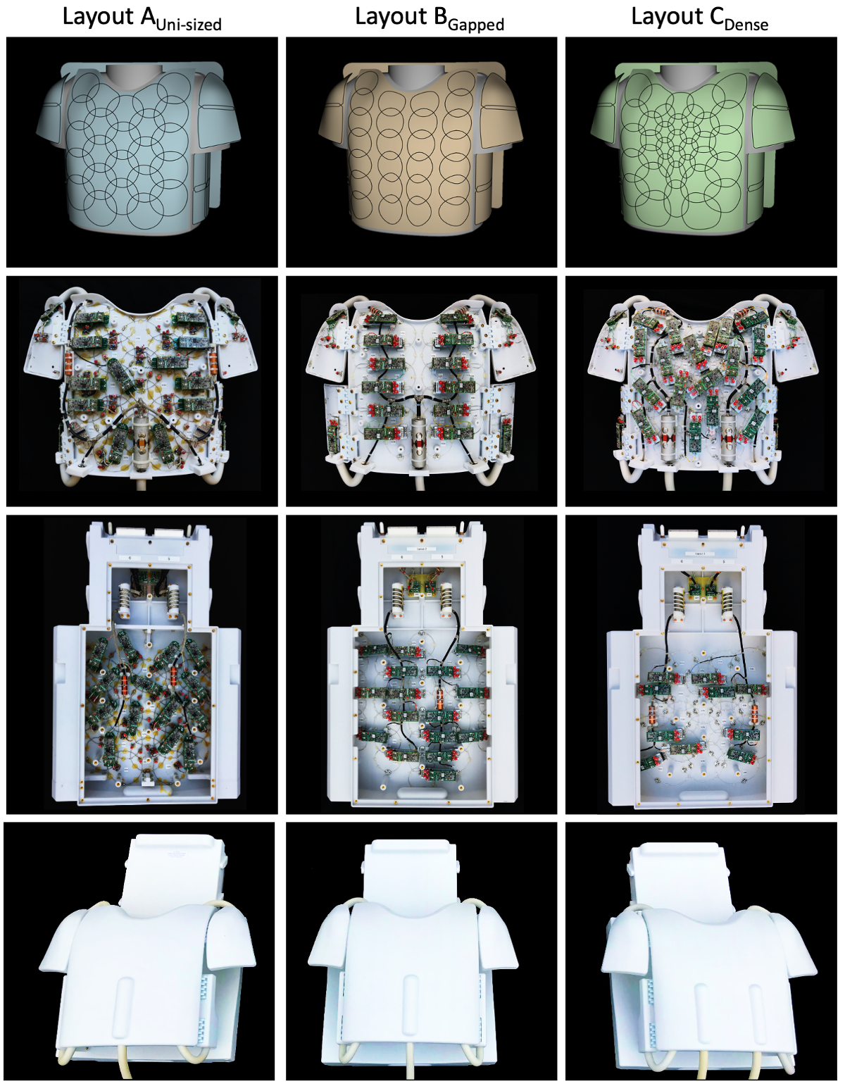
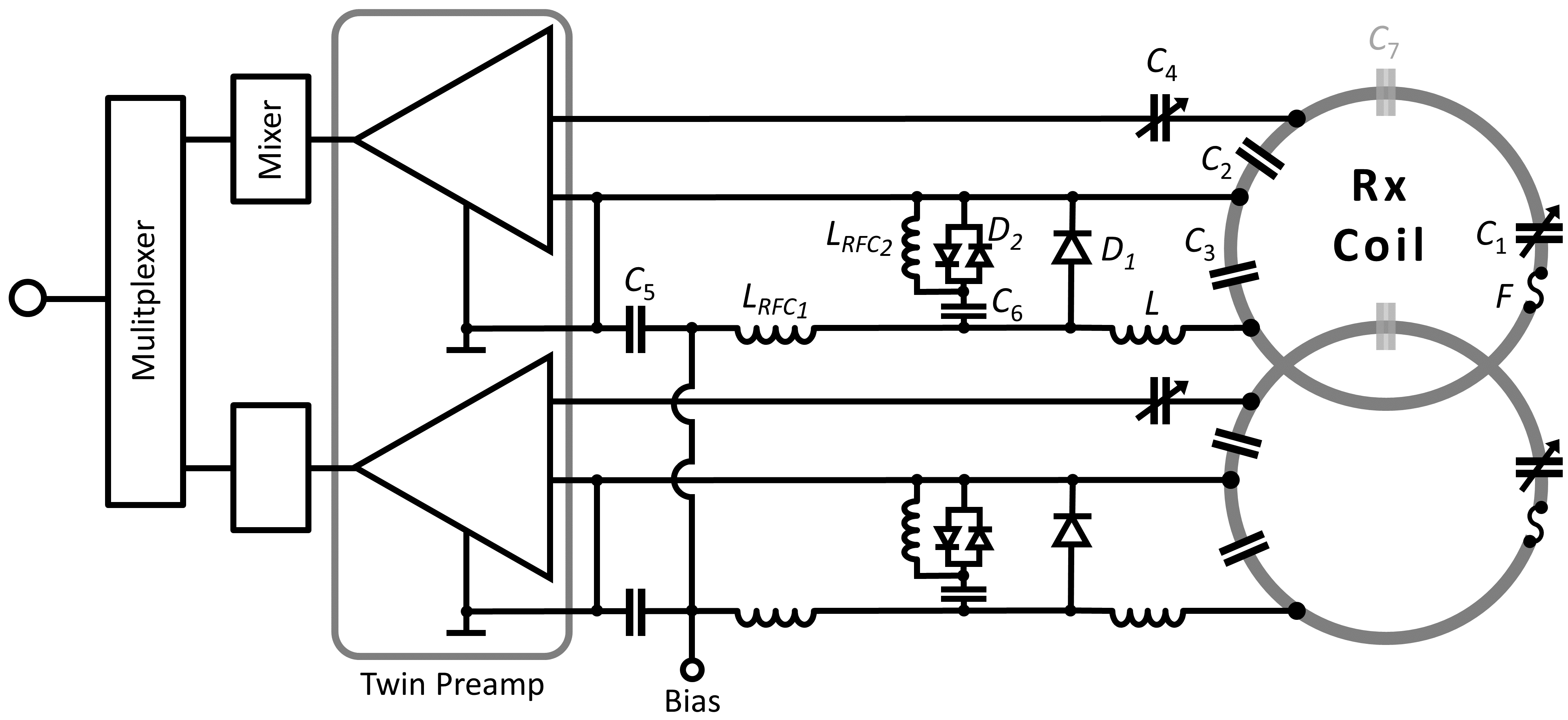
Coil Housing and Array Configuration: We designed, constructed, and validated three 64-channel array coils for 3T cMRI (Fig. 1). Uni-sized (A) is an overlapping design with uniformly distributed loops, 90 mm in diameter. Gapped (B) is a gapped design with uniformly distributed loops, 70 mm diameter. Dense (C) is an overlapped design varying the loop distribution density6, 50-130 mm diameter, with smaller elements centered over the heart (Fig. 1). All designs were constructed with identical body-shape adaptable housings that isolate the benefit of the native loop configurations in terms of signal-to-noise ratio (SNR) and image encoding. Design rules from our previous studies were followed7. Coils were designed for subject comfort with the anterior divided into five segments, with the main former linked to four adjustable lateral wings (shoulder and thorax), providing body shape adaptability and a snug fit. Housing parts were 3D printed from polycarbonate (Fortus 450mc, Stratasys, Eden Prairie, USA).Circuitry: Loop inductance was divided symmetrically with discrete component segments of tuning capacitors, and on the output circuit, matching capacitors and an active/passive detuning trap (Fig. 2). While decoupling from adjacent elements was addressed with critical overlap where possible, next-nearest neighboring coil elements were decoupled using preamplifier decoupling. This transformed the low impedance of the preamplifier to an open circuit in that loop8. Pairs of coils were attached to a twin preamplifier (Siemens Healthineers AG, Germany). Cable traps were placed on bundled output cables. Bench measurements verified QU/QL-ratios, element tuning, active/passive detuning, neighboring coupling, and preamplifier decoupling for all 192 contracted coil elements.
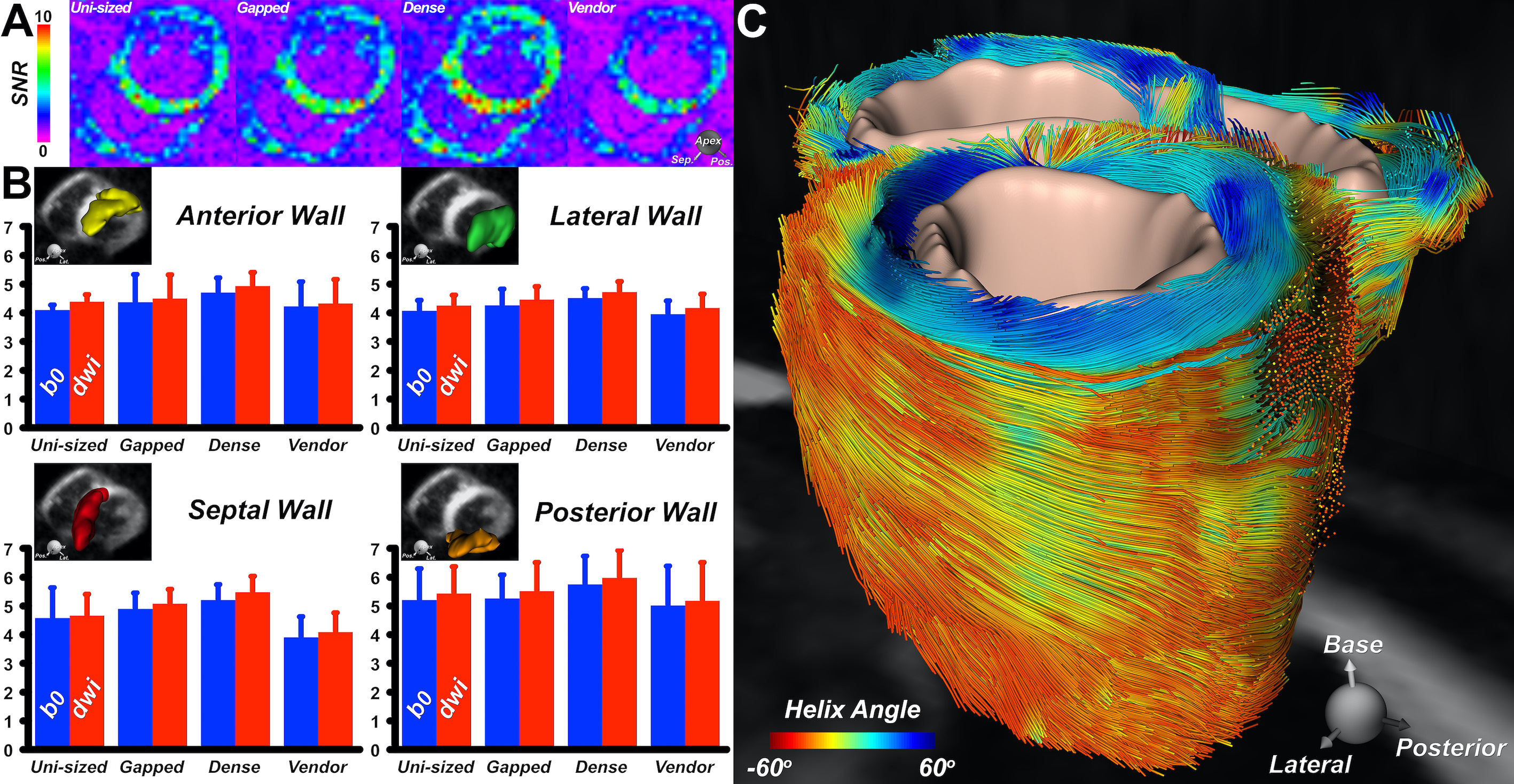
Data Acquisition: Validation was done on a 3T MRI system (Siemens Healthineers AG, Germany). The Siemens 38-channel product coil (Vendor, coil D) was included in all comparisons. The coils were compared for SNR and image encoding power, computed from a PD-weighted GRE raw data (TR/TE/α =200ms/4.03ms/20°, FoV=400mm, 10mm slice thickness, matrix size: 256x256), obtained using a torso phantom. Cardiac DTI was performed using each coil in a healthy volunteer. Imaging was performed during breathhold with an ECG-gated diffusion-encoded STE sequence. Acquisition parameters were: FOV=360x200mm2, resolution 2.5x2.5x8mm3, GRAPPA 2, TE=34ms, b-values=0 and 500s/mm2, 10 directions, and 8 averages. Reconstruction used spatiotemporal registration and entropy-based retrospective image selection3. SNR was calculated from the DW images9 in four segments of the left ventricular wall. Tractography was performed by integrating the primary eigenvector field into streamlines10.
Results
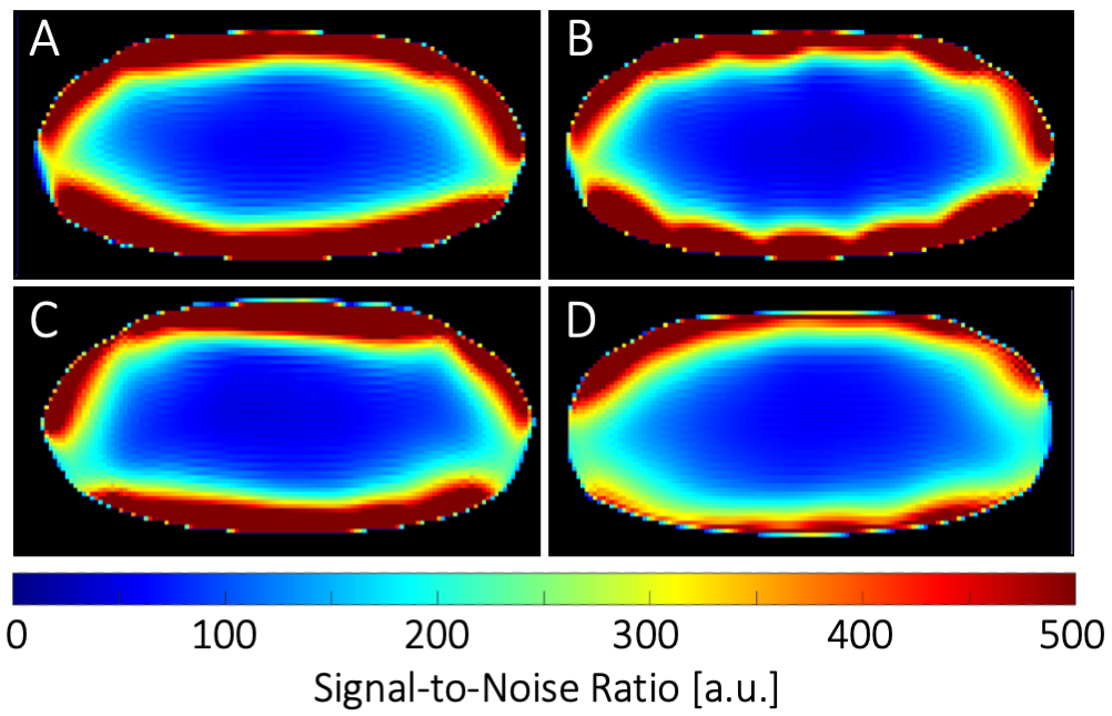
Seven different loop sizes 50mm to 90mm showed QU/QL-ratios ranging from 3.5 to 8.5, respectively. Thus, even small elements retained sample-noise dominance. Remaining coupling of adjacent loops ranged from −12dB to −21dB. Preamplifier decoupling provided an additional -22dB decoupling. The active PIN diode detuning showed >40dB isolation between the tuned and detuned states. SNR obtained from a representative plane though the phantom’s heart area showed similar values at the center for the Uni-sized, Dense, and Vendor cardiac coils (Fig. 3). However, the Gapped coil showed 14% less central SNR. When considering the whole heart area, the Dense coil outperformed the Uni-sized, Gapped, and Vendor coils with an SNR increase of 5%, 14% and 25%, respectively. Measurements at phantom regions corresponding to mid-lateral wall, mid-septum, and apex showed an SNR gain of 1.05-, 1.02-, and 1.8-fold, respectively, when the Dense coil was compared to the Uni-sized coil. The corresponding SNR improvement was 1.1-, 1.06-, and 1.12-fold when the Dense coil was compared to the Gapped coil. Differences in the coils were visible in the in vivo scans of a healthy volunteer as shown in Fig. 5.Discussion
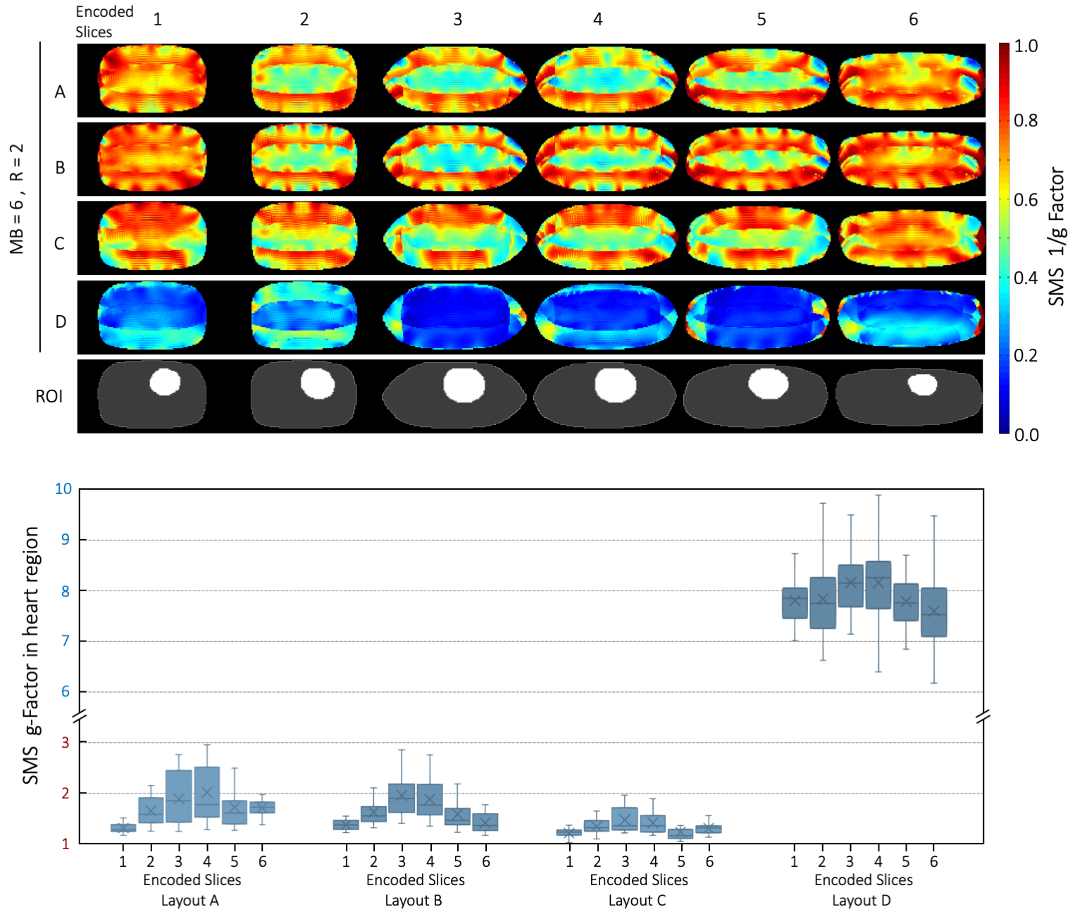
Three coils were designed and constructed, each with design characteristics that could provide superior performance for highly accelerated cDWI. The Dense coil configuration produced the highest sensitivity and best image encoding within the anatomic constraints of the heart. Encoding superiority was tested both in phantoms and in vivo by measuring the SNR. This superiority is attributed to the higher number of smaller array elements, located on the anterior surface close to the heart. Additionally, the larger elements, located further from the heart, provide better SNR at the target depth, compared to uniformly sized but smaller elements. Results from a healthy volunteer confirm the trend of the phantom measurements. Conclusive results require testing in additional subjects.Conclusion
Optimizing the coil array’s reception strategy to clinical targets results in enhanced cardiac image performance. This study indicates dedicated highly parallel cardiac arrays, such as the 64-channel coil with a non-uniform loop density configuration will be better suited than symmetrically distributed loop array layouts for highly accelerated in vivo cardiac SMS.Acknowledgements
No acknowledgement found.References
1. Setsompop K, Gagoski BA, Polimeni JR, Witzel T, Wedeen VJ, Wald LL. Blipped-controlled aliasing in parallel imaging for simultaneous multislice echo planar imaging with reduced g-factor penalty. Magn Reson Med. 2012;67(5):1210-1224.
2. Feinberg DA, Moeller S, Smith SM, et al. Multiplexed echo planar imaging for sub-second whole brain FMRI and fast diffusion imaging. PloS One. 2010;5(12):e15710.
3. Mekkaoui C, Reese TG, Jackowski MP, Cauley SF, Setsompop K, Bhat H, Sosnovik DE. Diffusion Tractography of the Entire Left Ventricle by Using Free-breathing Accelerated Simultaneous Multisection Imaging. Radiology. 2017 Mar;282(3):850-856.
4. Pruessmann KP, Weiger M, Scheidegger MB, Boesiger P. SENSE: sensitivity encoding for fast MRI. Magn Reson Med. 1999;42(5):952-962.
5. Griswold MA, Jakob PM, Heidemann RM, et al. Generalized autocalibrating partially parallel acquisitions (GRAPPA). Magn Reson Med. 2002;47(6):1202-1210.
6. King SB, Smith MJ, Matwiy J, Lin H-Y, Tomanek B. 31-Channel 3T Cardiac Array Optimized for SNR and g-Factor. In: Proc. Intl. Soc. Mag. Reson. Med.; 2012. #2647.
7. Etzel R , Cao X , Mekkaoui C , Sosnovik DE , Reese TG , Schuppert M , Schreiber LM, Fiebich M, Wald LL, Keil B. Design Optimization and Evaluation of a 64-Channel Cardiac Array Coil at 3T. In: Proc. Intl. Soc. Mag. Reson. Med.; 2015:#1780.
8. Roemer PB, Edelstein WA, Hayes CE, Souza SP, Mueller OM. The NMR phased array. Magn Reson Med. 1990;16(2):192-225. doi:10.1002/mrm.1910160203.
9. Nielles-Vallespin S, Mekkaoui C, Gatehouse P, Reese TG, Keegan J, Ferreira PF, Collins S, Speier P, Feiweier T, de Silva R, Jackowski MP, Pennell DJ, Sosnovik DE, Firmin D. In vivo diffusion tensor MRI of the human heart: reproducibility of breath-hold and navigator-based approaches. Magn Reson Med. 2013 Aug;70(2):454-65.
10. Mekkaoui C, Huang S, Chen HH, Dai G, Reese TG, Kostis WJ, Thiagalingam A, Maurovich-Horvat P, Ruskin JN, Hoffmann U, Jackowski MP, Sosnovik DE. Fiber architecture in remodeled myocardium revealed with a quantitative diffusion CMR tractography framework and histological validation. J Cardiovasc Magn Reson. 2012 Oct 12;14(1):70.
Figures