0138
A non-resonant leaky-wave coil for UHF body imaging1The Department of Physics and Engineering, ITMO University, Saint Petersburg, Russian Federation, 2General and Theoretical Electrical Engineering (ATE), Faculty of Engineering and General and Theoretical Electrical Engineering (ATE), Faculty of Engineering, University of Duisburg-Essen, Duisburg, Germany, 3Center for Nanointegration Duisburg-Essen, Duisburg, Germany, 4Imaging Division, UMC Utrecht, Utrecht, Netherlands, 5Medical Image Analysis, Biomedical Engineering, Technical University of Eindhoven, Eindhoven, Netherlands
Synopsis
Ultra-high field (field strength higher than 7 Tesla) body imaging is an extensively developing field. Since at such Larmor frequencies of 298 MHz or higher volume (birdcage or TEM) coils are not efficient due to interference effects, surface or volume transmit arrays are commonly used. To obtain homogenous filed in ROI so-called RF-shimming procedure is commonly used. In this work, we present a new radiative RF-coil array for UHF MRI of the human body, based on a wideband non-resonant leaky wave antenna.
Purpose
To develop and characterize both numerically and experimentally novel and power-efficient non-resonant array elements with improved SAR performance.Introduction
Leaky-wave antennas (LWAs) are well known in the microwave frequency range as low-profile and robust solutions with a simple design and frequency beam steering [3]. The working principle of LWAs is based on radiation of power to free space due to propagation of a fast travelling wave along the antenna with complex propagation constant. This means that power is radiated continuously along with the antenna which is typically a periodic structure of small radiators in a transmission line with an electrically-small period (so-called quasi-uniform leaky-wave antennas) [3]. Practically that means that each unit cell the periodic structure consists of a small radiator that consumes a portion of the traveling wave's power and converts it to radiation. When power is applied to the input, all radiators are fed by the transmission line series with a linear phase shift. When properly designed the transmission line supports propagation without reflections and eventually radiate the most of the input power before the wave arrives at the end of the line. Using this approach, we developed a novel surface transmit array element for UHF prostate imaging.Methods
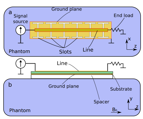
The design of the proposed LWA is presented in Figure 1. It consists of an air-filled microstrip line with six I-shaped slots etched in the ground plane. A slot and section of the transmission line just above it form a unit cell of the periodic structure of the antenna. One port of the antenna should be connected to the scanner interface while the other should be loaded to a high-power load to dissipate the residual power radiated to the medium of the phantom and dissipated within. The total length of the slots, period of unit cell and height of transmission line were optimized to provide broadband non-resonant excitation of B1 field. Because on of non-resonant excitation, the level of SAR at the surface was substantially lower than for fractionated dipole. For safety evaluation, simulations were performed using Duke voxel model in a 4-channel array configuration with phase-only static shimming applied to the prostate region. MRI experiments with phantom and in-vivo were performed using Philips Achieva 7 Tesla MRI platform in UMC Utrecht, Netherlands. Fractionated dipole was used as a reference coil [2]. All in-vivo studies were approved by a local ethic committee.Results
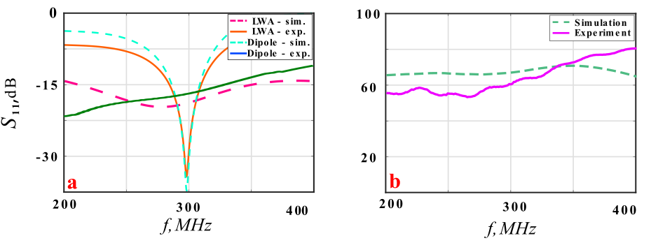
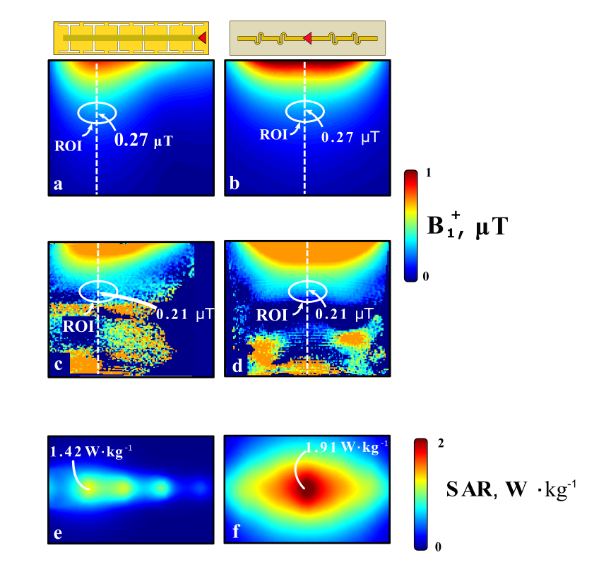
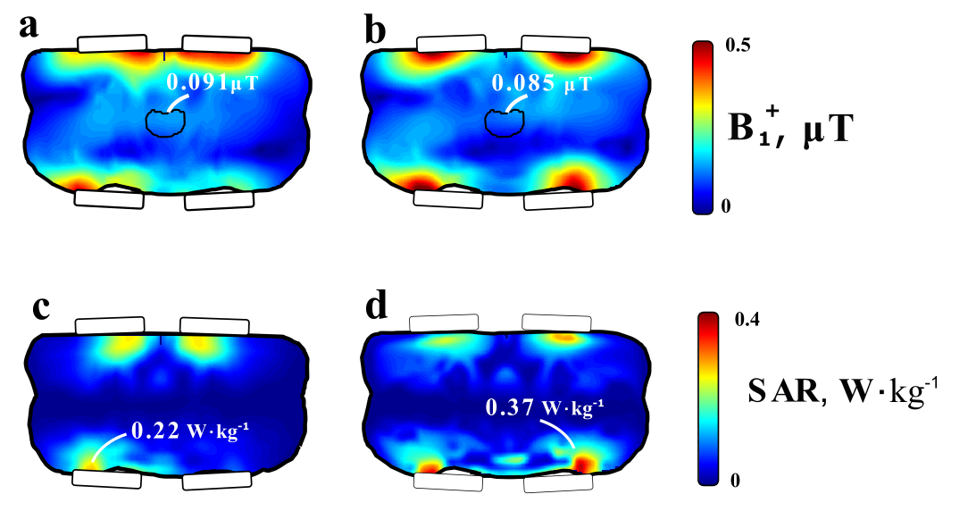
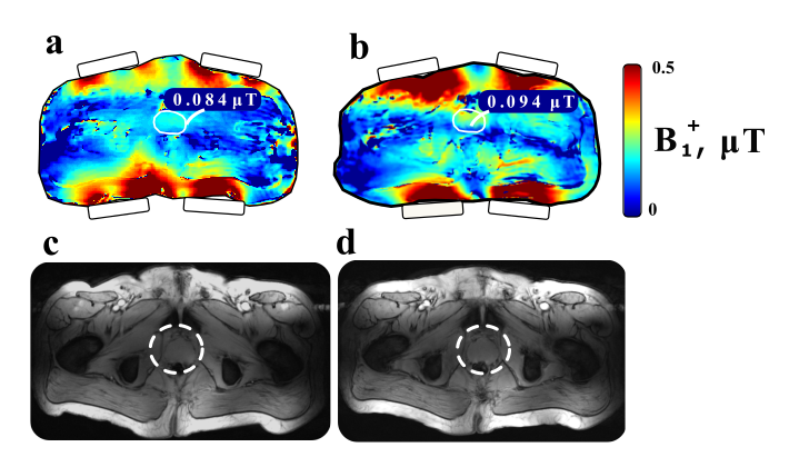
Figure 2 (a) demonstrates the behavior of the simulated and measured reflection coefficient at the input S11 over the frequency range from 200 to 400 MHz It shows that the LWA has good matching in frequency from 200 to 400 MHz . However, since LWA is a two-port device, it is also important to control the level of S12 between the input and output, which is determined by the level of power absorbed in the phantom and input impedance matching. Simulated and measured absorbed power are shown in Figure 2 (b). In the experiment, the level of power was 60 %, i.e., not all power was absorbed in the phantom. However, simulations and measurements (Figure 3) using homogenous phantom showed that the B1 field of the LWA was equal to that of the dipole at the depth of the 7 cm and below while keeping a level of SAR 34 % lower than for the fractionated dipole. Figure 4 (a-c) demonstrates simulated B1 and SAR using Duke voxel model both for the LWA and dipole arrays. LWA array created 8 % lower B1 than the dipole while keeping the level of local SAR10g maximum 40 % lower. In-vivo B1 maps and T2-weighed images are shown in Figure 5 (a-d). In-vivo B1 averaged over the prostate region was 11 % lower for LWA-array than for fractionated dipoles while keeping a tolerable level of image quality.Conclusion
We developed a novel concept of an antenna for UHF body imaging at 7 Tesla. Because of non-resonant behavior, the local SAR maximum value was lower than for a fractionated dipole array while keeping almost the same level of B1 field in the region of interest. Such leaky-wave approach could be used in UHF body imaging at 7 Tesla and, potentially, even higher field strengths (9.4 and 10.5 Tesla).Acknowledgements
This project received funding from the European Union’s Horizon 2020 research, innovation program under grant agreement no. 736937 and the Russian Foundation for Basic Research (19-29-10038).References
1. D. R. Jackson, C. Caloz, T. Itoh. "Leaky-Wave Antennas". Proceedings of the IEEE 2012; 100(7):2194-2206.
2.Raaijmakers, A, Italiaander, M, Voogt, I, Luijten, P, Hoogduin, J, Klomp, D, Berg, C. "The fractionated dipole antenna: A new antenna for body imaging at 7 Tesla". Magnetic Resonance in Medicine 2016; 75(3):1366-1374.
3. Vaughan, J, Snyder, C, DelaBarre, L, Bolan, P, Tian, J, Bolinger, L, Adriany, G, Andersen, P, Strupp, J, Ugurbil, K. "Whole-body imaging at 7T: Preliminary results". Magnetic Resonance in Medicine 2009; 61(1):244-248.
Figures