0136
Self-tuning stretchable RF receive coil concept using liquid metal encapsulated within an elastic polymer
Elizaveta Motovilova1,2, Jana Vincent3, Victor Taracila3, Fraser Robb3, Ek Tsoon Tan2, James Shin1, Hollis G. Potter2, Darryl B. Sneag2, and Simone Angela Winkler1
1Radiology, Weill Cornell Medicine, New York, NY, United States, 2Radiology, Hospital for Special Surgery, New York, NY, United States, 3GE Healthcare, Aurora, OH, United States
1Radiology, Weill Cornell Medicine, New York, NY, United States, 2Radiology, Hospital for Special Surgery, New York, NY, United States, 3GE Healthcare, Aurora, OH, United States
Synopsis
Commercial coils, built to accommodate a wide range of anatomical dimensions, are rigid and of fixed size, thus yielding sub-optimal SNR and patient comfort. Existing flexible/stretchable solutions suffer from resonance detuning due to inductance changes under stretch/deformation. In this work, we propose an alternative coil concept using liquid metal microchannel conductors encapsulated in a stretchable polymer matrix. We developed a self-tuning coil using a stretchable, adaptively compensating, interdigital capacitor. We observed a <0.5% of frequency stability in silico and in vitro. In vivo results were demonstrated on 3T wrist imaging.
Background and Purpose
Commercial RF coils are often built to accommodate a wide range of anatomical dimensions, which can result in large offset distances of the coil from the target anatomy and yield sub-optimal SNR. Recent progress in flexible 1-12 and stretchable 13-20 RF coil design has demonstrated improved sensitivity and enhanced patient comfort due to increased conformity. However, stretchable coils suffer from resonance detuning due to the inherent lengthening of conductors under tension that increase inductance. The proposed methods to mitigate this effect, such as wide-band matching 16,21,22 and automatic tuning/matching circuitry 17, can dramatically increase circuit complexity and thus make reliability and implementation difficult. In this work, we explore an alternative design of a stretchable RF coil (Figure 1a) based on liquid metal conductors encapsulated in a soft, elastic, polymer. A liquid metal interdigital capacitor is proposed and its parameters are optimized to compensate for inductance changes. This imparts self-tuning capability under stretching that allows the coil to adapt to various anatomical shapes without the need for frequency readjustments.Methods
Theory and optimizationThe frequency shift in an RF coil can be understood via the resonance equation, $$$f_0=1/(2\pi\sqrt{LC})$$$, where $$$f_0$$$ is the resonance frequency, and $$$L$$$ and $$$C$$$ are the total inductance and capacitance of the coil, respectively. The total self-inductance of a loop coil increases approximately linearly under a unidirectional stretch $$$\alpha$$$, $$$L=\alpha L_0+\mu_0\mu_r(3D/4)\alpha\ln\alpha$$$ 23. To mitigate this frequency shift, we use an interdigital capacitor that decreases its capacitance under stretch. The total capacitance of an interdigital capacitor stretched by a factor $$$\alpha$$$, applied perpendicular to the fingers, is $$$C=C_0/\sqrt{\alpha}$$$ 24,25. Figure 1b shows the theoretical changes of coil inductance and capacitance under a stretch applied along the transverse direction (x-axis). Combining $$$L$$$ and $$$C$$$, this coil design compensates for inherent increase in inductance and thereby reduces frequency shift over a wide range of degrees of stretch. Using this theoretical analysis as a starting point, optimized coil parameters and dimensions for the interdigital capacitor design were obtained from a more comprehensive 3D electromagnetic analysis (COMSOL Multiphysics) for a coil size of 7cm×8cm, yielding: number of digits N=8, digit length b=7mm, inter-digit spacing g=0.5mm, and conductor width w=0.5mm (Figure 2a).
Coil construction
Plastic molds that contain a layout of conductive traces of the desired coil geometry were fabricated using a 3D printer (Prusa i3 MK3S) and polylactic acid (PLA) material. Ecoflex® elastomer was used to create a microchannel-integrated polymer matrix. Liquid metal (eutectic GaIn alloy) was injected into the embedded microchannels using a needle and syringe to form conducting traces (Figure 3a). Copper wires were inserted at the terminals and connected to a printed circuit board containing tuning, matching, detuning, and preamplifying circuitry. A “conventional” but stretchable reference coil using a fixed value lumped element capacitor was fabricated to analyze self-tuning performance.
Bench tests
Both coil prototypes were tested on the bench under stretch using a vector network analyzer (Keysight E5071C) and a custom-built unidirectional stretching test setup. The coils were linearly stretched from 0% to 30% with a step size of 5%, and S11 values were recorded. This maximum stretch degree was chosen to demonstrate as a proof-of-concept the potential of the proposed coil design to undergo considerable stretching without significant frequency detuning, however, coil design can be further optimized for other stretching levels.
Imaging
All experiments were performed on a 3T GE MR750 system. For in vitro experiments, the coil was loaded with a standard homogeneous cylindrical phantom (Lph=21cm, Rph=6cm, 4.42g CuSO5H2O, 9.95g NaCl, 2.21L distilled water). For in vivo experiments, informed consent was obtained from a healthy volunteer under a locally approved institutional review board protocol. Images were acquired under 0% and 20% of coil stretch (Figure 4ac). Phantom images were acquired using a gradient echo (GRE) sequence (TR/TE=500/6.9ms, FA=25°, voxel size=1×1×5mm3, NEX=1). In vivo GRE images of the wrist in a healthy volunteer were acquired (TR/TE=1800/27.3ms, FA=30°, voxel size=1×1×5mm3, NEX=2).
Results
Figure 2b shows simulated S11 parameter changes under stretch for reference and proposed coils; and (c)-(e) shows simulated sensitivity maps of the proposed coil with cylindrical loads of diameters 10cm, 11cm, and 12cm at 128 MHz. Figure 3b shows the simulated/measured resonance frequency shift under stretch for the reference and proposed coils. Figure 4bd shows 2D axial proton density MR images for 0 and 20% of stretch. The Ecoflex material appears bright on the image. Excellent SNR was observed in both cases with minimal degradation of the maximum SNR value (5%) while the average SNR value improved by 3% due to the increased field-of-view when measured at 3cm depth inside the load (Figure 4e). Figure 4f shows a successful first in vivo wrist image using the proposed single-element design.Conclusions
Based on the study’s results, it is feasible to construct a soft and stretchable receive coil that conforms to a desired anatomy and can be stretched to a significant degree (up to 30%) without the need for retuning electronics. We observe a maximum measured frequency shift of 0.4% with up to 30% of stretch, as well as <5% in vitro SNR degradation for a 20% stretch. Future work will include optimization of material parameters and multi-channel coil decoupling strategies.Acknowledgements
This work was supported by the National Institutes of Health (NIH R00EB024341) and GE Healthcare.References
- Corea JR, Flynn AM, Lechêne B, Scott
G, Reed GD, Shin PJ, Lustig M, Arias AC. Screen-printed flexible MRI receive
coils. Nature communications 2016;7(1):1-7.
- Winkler SA, Corea J, Lechêne B, O’Brien K, Bonanni JR, Chaudhari A, Alley M, Taviani V, Grafendorfer T, Robb F. Evaluation of a flexible 12-channel screen-printed pediatric MRI coil. Radiology 2019;291(1):180-185.
- Jia F, Yuan H, Zhou D, Zhang J, Wang X, Fang J. Knee MRI under varying flexion angles utilizing a flexible flat cable antenna. NMR in Biomedicine 2015;28(4):460-467.
- Mager D, Peter A, Del Tin L, Fischer E, Smith PJ, Hennig J, Korvink JG. An MRI receiver coil produced by inkjet printing directly on to a flexible substrate. IEEE transactions on medical imaging 2010;29(2):482-487.
- Zhang B, Sodickson DK, Cloos MA. A high-impedance detector-array glove for magnetic resonance imaging of the hand. Nature biomedical engineering 2018;2(8):570-577.
- Vasanawala SS, Stormont R, Lindsay S, Grafendorfer T, Cheng JY, Pauly JM, Lustig M, Scott G, Guzman JX, Taracila V, Chirayath D, Robb F. Development and Clinical Implementation of Very Light Weight and Highly Flexible AIR Technology Arrays. The ISMRM 25th Annual Meeting & Exhibition. Honolulu, HI, USA2017.
- AIR Technology.
https://www.gehealthcare.com/products/magnetic-resonance-imaging/air-technology (accessed on 15 Dec 2020).
- Stickle Y-J, Follante C, Giancola M, Anderson D, Robb F, Taracila V, Stormont R, Blahnik H, Winkler S, Sneag D. A Novel Ultra-Flexible High-Resolution AIR (Adaptive imaging receive) 64-Channel Bilateral Phased Array for 3T Brachial Plexus MRI. ISMRM & SMRT Virtual Conference2020.
- Nohava L, Czerny R, Obermann M, Pichler M, Frass-Kriegl R, Felblinger J, Ginefri J-C, Laistler E. Flexible multi‐turn multi‐gap coaxial RF coils (MTMG‐CCs): design concept and bench validation. 2019. p 0565.
- Czerny R, Nohava L, Frass‐Kriegl R, Felblinger J, Ginefri J, Laistler E. Flexible multi‐turn multi‐gap coaxial RF coils: enabling a large range of coil sizes. 2019. p 1550.
- Hosseinnezhadian S, Frass-Kriegl R, Goluch-Roat S, Pichler M, Sieg J, Vít M, Poirier-Quinot M, Darrasse L, Moser E, Ginefri J-C. A flexible 12-channel transceiver array of transmission line resonators for 7 T MRI. Journal of Magnetic Resonance 2018;296:47-59.
- Ruytenberg T, Webb A, Zivkovic I. Shielded‐coaxial‐cable coils as receive and transceive array elements for 7T human MRI. Magnetic resonance in medicine 2020;83(3):1135-1146.
- Nordmeyer‐Massner JA, De Zanche N, Pruessmann K. Stretchable coil arrays: application to knee imaging under varying flexion angles. Magnetic resonance in medicine 2012;67(3):872-879.
- Gruber B, Zink S. Anatomically adaptive local coils for MRI Imaging–Evaluation of stretchable antennas at 1.5 T. 2016. p 543.
- Varga M, Mehmann A, Marjanovic J, Reber J, Vogt C, Pruessmann KP, Tröster G. Adsorbed eutectic GaIn structures on a neoprene foam for stretchable MRI coils. Advanced Materials 2017;29(44):1703744.
- Mehmann A, Varga M, Vogt C, Port A, Reber J, Marjanovic J, Pruessmann KP, Tröster G. On the bending and stretching of liquid metal receive coils for magnetic resonance imaging. IEEE Transactions on Biomedical Engineering 2018;66(6):1542-1548.
- Mehmann A, Vogt C, Varga M, Port A, Reber J, Marjanovic J, Pruessmann KP, Sporrer B, Huang Q, Tröster G. Automatic resonance frequency retuning of stretchable liquid metal receive coil for magnetic resonance imaging. IEEE transactions on medical imaging 2018;38(6):1420-1426.
- Gruber B, Rehner R, Laistler E, Zink S. Anatomically Adaptive Coils for MRI—A 6-Channel Array for Knee Imaging at 1.5 Tesla. Frontiers in Physics 2020;8:80.
- Vincent J, Rispoli JV. Conductive thread-based stretchable and flexible radiofrequency coils for magnetic resonance imaging. IEEE Transactions on Biomedical Engineering 2019.
- Port A, Luechinger R, Brunner DO, Pruessmann KP. Conductive Elastomer for Wearable RF Coils. 2020.
- Nordmeyer‐Massner JA, De Zanche N, Pruessmann KP. Mechanically adjustable coil array for wrist MRI. Magnetic Resonance in Medicine: An Official Journal of the International Society for Magnetic Resonance in Medicine 2009;61(2):429-438.
- Port A, Albisetti L, Varga A, Marjanovic J, Reber J, Brunner D, Pruessmann K. Liquid metal in stretchable tubes: a wearable 4‐channel knee array. 2019. p 1114.
- Paul CR. Inductance: loop and partial: John Wiley & Sons; 2011.
- Fassler A, Majidi C. Soft-matter capacitors and inductors for hyperelastic strain sensing and stretchable electronics. Smart Mater Struct 2013;22(5).
- Igreja R, Dias C. Analytical evaluation
of the interdigital electrodes capacitance for a multi-layered structure.
Sensors and Actuators A: Physical 2004;112(2-3):291-301.
Figures
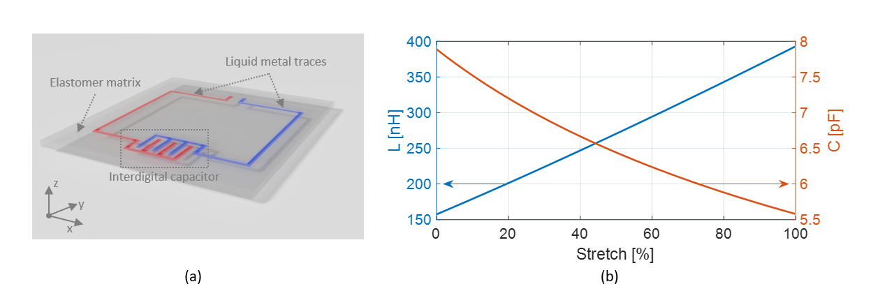
Figure 1. (a) Conceptual drawing of the
proposed RF coil element. (b) Inductance and capacitance changes with stretch.
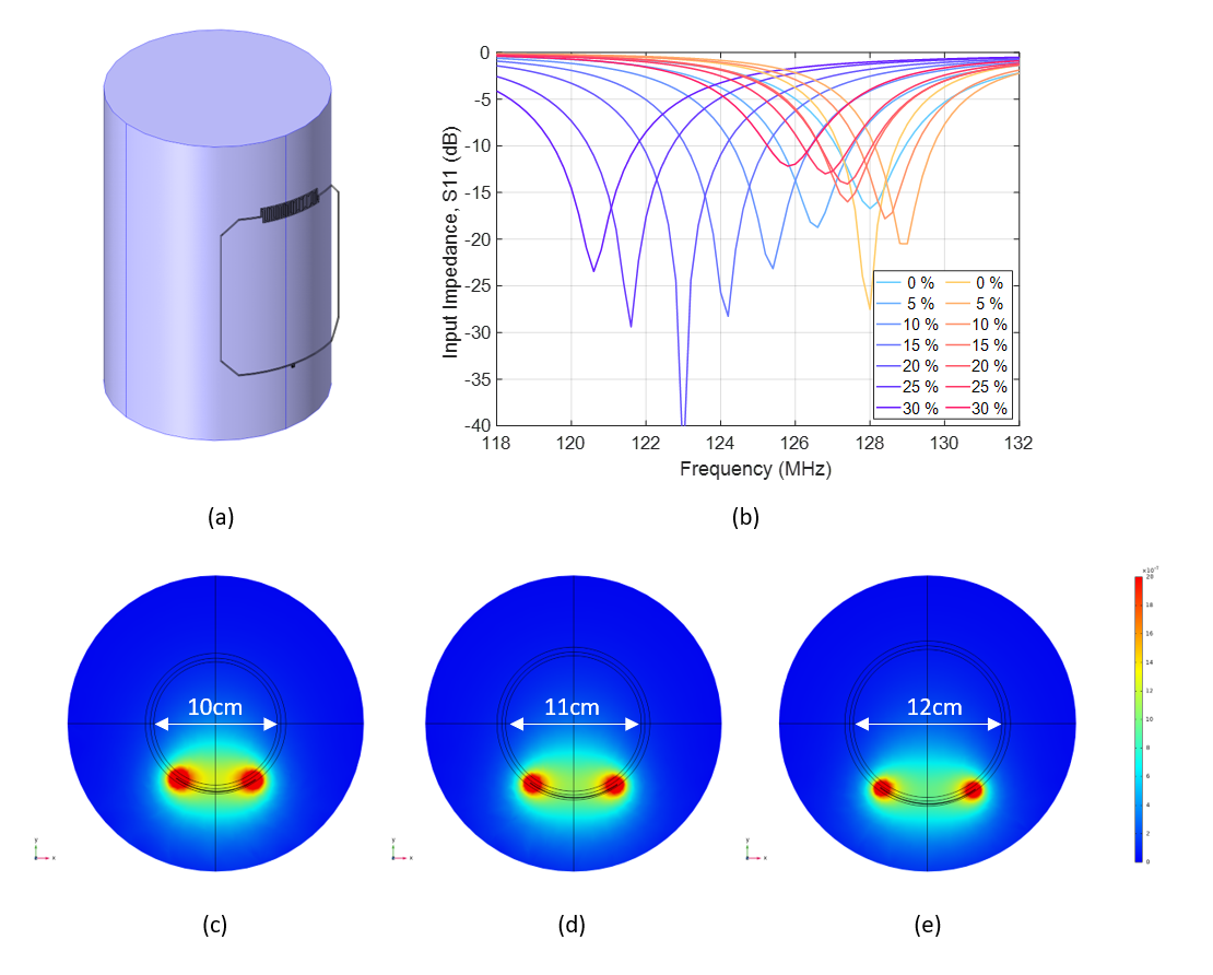
Figure 2. (a) 3D model of the proposed coil
loaded with a homogeneous cylindrical phantom (Lph=15cm, Rph=5cm, epsr=78, sigma=0.46S/m). (b) Numerical simulations of the S11 parameter
changes under stretch for the proposed (shades of red) and reference (shades of
blue) coils. Simulated sensitivity maps of the proposed coil with load
diameter varying from (c) 10cm to (d) 11cm to (e) 12cm.
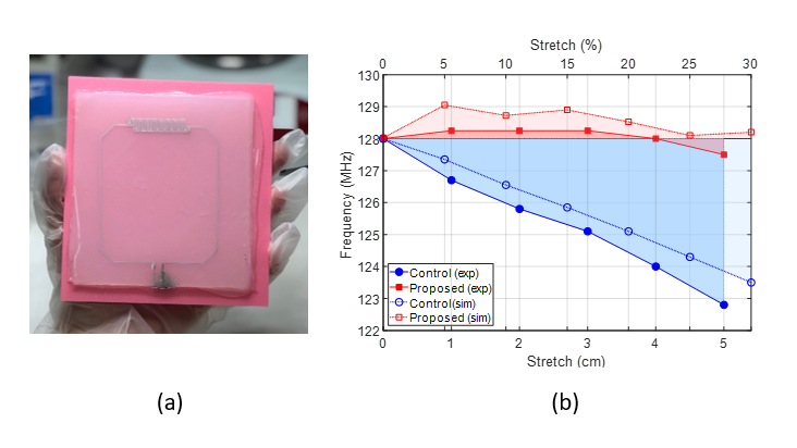
Figure 3. (a) Fabricated prototype of
stretchable self-tuning coil. (b) Simulated (open markers) and measured
(filled markers) frequency changes with stretching of the reference (blue) and
proposed (red) coils.
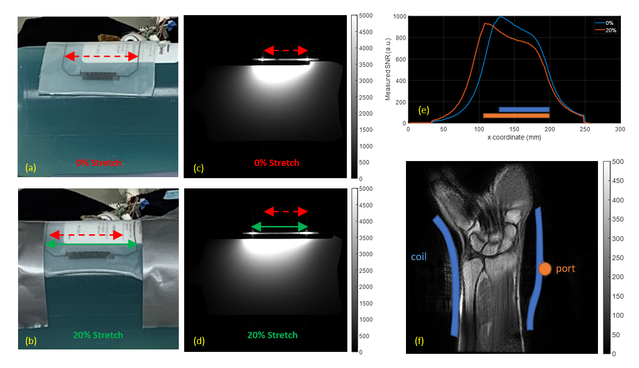
Figure 4. Photographs of the proposed coil in
(a) unstretched and (c) 20% stretched positions and (b), (d) the corresponding sensitivity
profiles. (e) Normalized SNR of the relaxed (blue) and 20% stretched (orange)
coil as measured transversally at the depth of 3cm inside the load. The color
bars illustrate approximate width of the relaxed (blue) and stretched (orange)
coil. (f) First in vivo MR image of a wrist made with the proposed coil.