0134
Metasurface for B1+ homogenization in abdominal MRI at 3T1ITMO University, Saint-Petersburg, Russian Federation, 2Federal Almazov North-West Medical Research Center, Saint-Petersburg, Russian Federation, 3Universidad Nacional de Colombia, Bogota, Colombia
Synopsis
A novel approach for improving B1+ homogeneity in the abdominal area at 3T MRI is proposed and demonstrated numerically and experimentally. The approach is implemented via the ultralight and thin metasurface. The metasurface consists of metal wires loaded with capacitors printed on a flexible dielectric substrate of polyimide. Numerical studies and imaging of a volunteer covered with the proposed metasurface showed the same homogeneity of the transmit radiofrequency field distribution at the region-of-interest as the conventional dielectric pads.
Introduction
Radiofrequency (RF) magnetic field inhomogeneity is a significant concern for imaging of large fields-of-view at 3T MRI. The wavelength of the RF field gets shortened to ~26 cm when measured in the body. It leads to the RF magnetic field’s constructive or destructive interference that implies local areas with a brighter and darker signal.1 High-permittivity dielectric pads2, consisting of mixed ceramic powders and heavy water, have been shown to increase the RF magnetic field in low-transmit efficiency regions at high and ultra-high magnetic fields. However, dielectric pads have several drawbacks: change of the dielectric constant with time, bio-incompatibility of some constituents, and weight of up to several kilograms.3 Recently, an artificial dielectric metamaterial that mitigates those disadvantages has been shown feasible for imaging of parietal lobes at 7T.4,5 Here, we demonstrate via simulations and in vivo study the ultralight and thin metasurface to improve abdominal imaging at 3T and compare its performance with the conventional dielectric pad.Methods
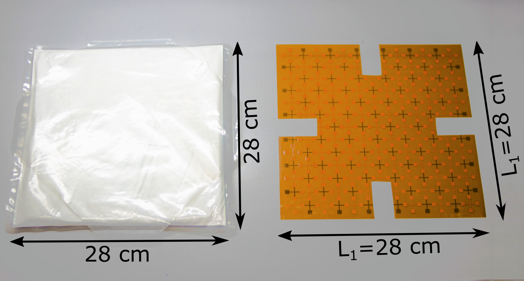
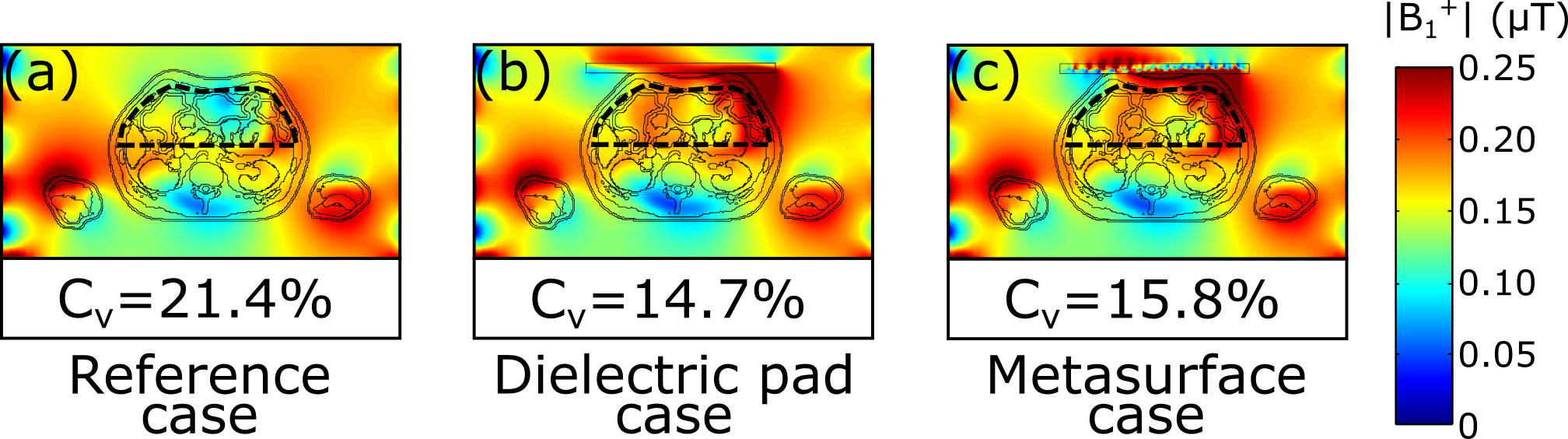
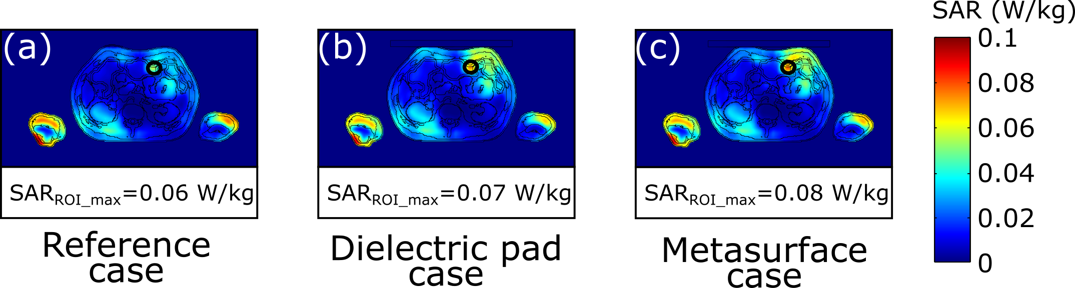
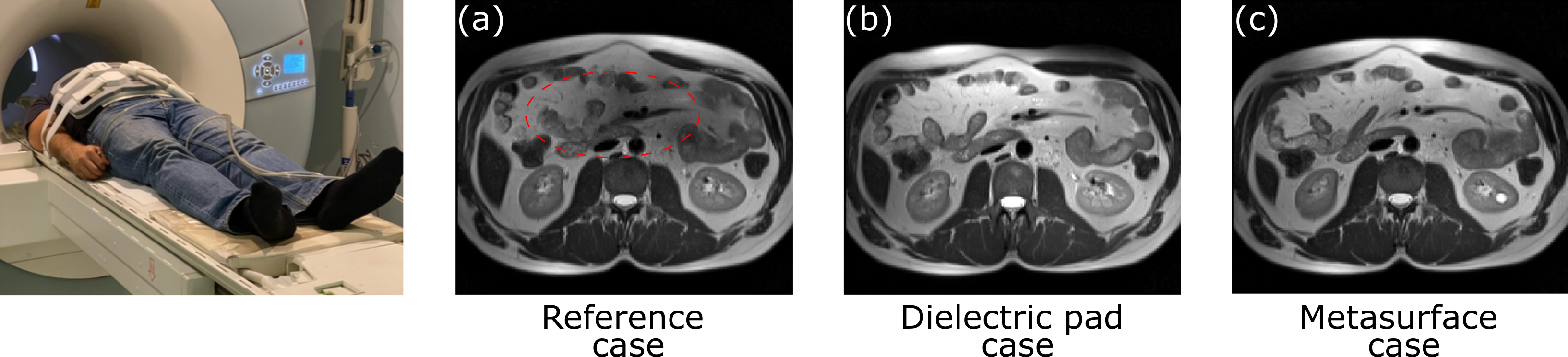
The metasurface is shown in Figure 1. The metasurface is organized as a two-dimensional periodic stricture of cross copper strips (18 μm thick) ended with square copper patches (with sizes of 5.76×5.76 mm2). The neighboring crosses are printed on the opposite sides of a flexible dielectric substrate (Dupont Pyralyx AP8515R with a thickness of 25 μm and ɛ = 3.4), and their patches produce parallel-plate capacitors (C = 40 pF). The overall metasurface dimensions are L1×L1 = 28×28 cm2. The period and the capacitance of the metasurface were chosen to achieve the same phase velocity of the wave propagating along the surface and having an electric field polarized along with the patches as for the conventional dielectric pad6 (dimensions of 28×28×1.5 cm3, ɛr = 300, and σ = 0.4 S/m). Those conditions correspond to excitation by a body coil of the structure positioned over the human body’s abdominal region. In other words, the metasurface provides the same phase delay as the conventional pad. All numerical simulations were performed in CST Microwave Studio. The transmit RF field’s distribution inside the voxel model (“Gustav” with BMI = 22.3 kg/m2) and a two-port high pass shielded body birdcage coil tuned to 128 MHz was simulated for three cases: (1) without any pad (i.e., reference case), with (2) conventional dielectric pad and (3) metasurface placed on the abdomen. The body coil diameter was 70 cm, length – 49 cm. The figure-of-merit of field homogeneity is the coefficient of variation Cv defined as the standard deviation of B1+ over its mean value in the region-of-interest (ROI).7 The ROI is shown by the dashed black line (Figure 2). The SAR (10g averaged) and B1+ maps were calculated for 1W of accepted power. Experimental data were acquired with a Siemens Magnetom Trio 3T whole-body MRI scanner using a T2-weighted HASTE sequence. The receive coil used for the acquisition was Body Matrix Coil (Siemens). The high-permittivity dielectric pad (left panel in Figure 1) was based on CaTiO3 ceramic powder mixed with heavy water. The dielectric pad and the metasurface had the same geometric and material parameters as in the simulations. A male volunteer with BMI = 28.6 kg/m2 was investigated.Results
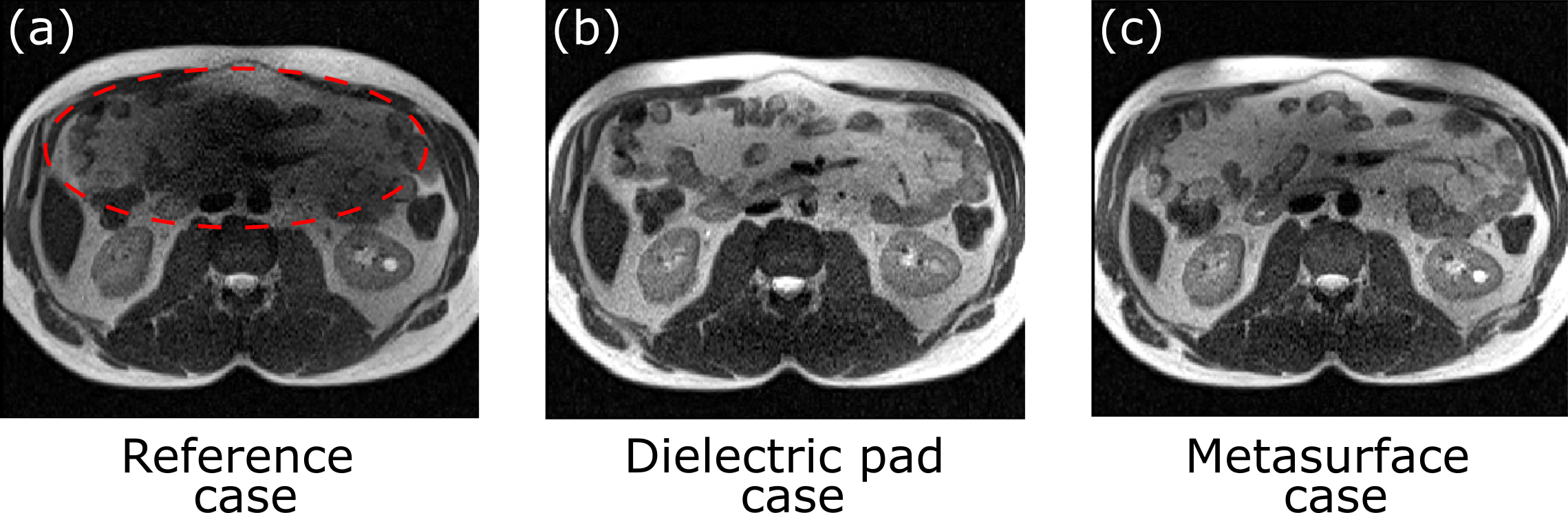
Figure 2 shows simulated B1+ maps for three cases: (1) without any pad (i.e., reference case), with (2) conventional dielectric pad, and (3) metasurface placed on the abdomen. One can observe the B1+-field inhomogeneity in the ROI for the reference case (Figure 2a). The addition of the pad and the metasurface improves the B1+-field in ROI (Figure 2b,c), which is confirmed by the decrease in figure-of-merit by ~6% for both cases as compared to the reference case. Figure 3 illustrates simulated local SAR in the same cross-section where the field B1+ was shown. Note that the addition of the pad or the metasurface does not significantly increase local SAR in ROI. Maximum SAR was located in the right arm, and it was 0.11 W/kg for all three cases. Experimentally obtained MR images of a volunteer in the axial plane are shown in Figure 4 and Figure 5. First, the birdcage coil was used to transmit and Body Matrix Coil to receive (Figure 4), whereas, in Figure 5, we used the birdcage coil for both transmit and receive modes. In Figure 4a, one can see a dark region in the abdomen’s top area. The dielectric pad (Figure 4b) or the metasurface (Figure 4c) brings brightness into the dark region. The same effect is observed in Figure 5, where the reference case’s dark region is even larger.Discussion and conclusion
The metasurface has been designed to improve the homogeneity of clinical MRI 3T abdominal imaging. Its effect is similar to the high-permittivity dielectric pad. However, the metasurface is based on polyimide material, that is ultralight, cheap, and flexible, marking the proposed metasurface’s advantages. By adjusting the sizes of the printed parallel-plate capacitors in the metasurface unit cells, one can achieve equivalence to different values of permittivity of conventional pads also used in other imaging applications. For instance, a similar metasurface can be implemented to solve other imaging problems caused by the dielectric artifact (i.e., fetal, heart imaging) and at the other static magnetic field strength.Acknowledgements
This work was supported by the Russian Science Foundation (Grant No. 18-79-10167). The authors thank Dr. ir. Wyger Brink for assistance with dielectric pad fabrication.References
1. Christianson KL et al. Duke Review of MRI Principles: Case Review Series. 2012.
2. Teeuwisse WM et al. Simulations of high permittivity materials for 7 T neuroimaging and evaluation of a new barium titanate-based dielectric. Magn Reson Med. 2012;67(4): 912-918.
3. Neves AL et al. Compressed perovskite aqueous mixtures near their phase transitions show very high permittivities: New prospects for high-field MRI dielectric shimming. Magn Reson Med. 2018;79(3): 1753-1765.
4. Vorobyev V et al. An artificial dielectric slab for ultra high-field MRI: Proof of concept. Journal of Magnetic Resonance. 2020; 320: 106835.
5. Vorobyev V et al. Design and demonstration of an artificial dielectric for 7 T MRI. 2020. ISMRM & SMRT Virtual Conference & Exhibition 2020.
6. van Gemert et al. A simulation study on the effect of optimized high permittivity materials on fetal imaging at 3T. Magnetic resonance in medicine. 2019; 82(5): 1822-1831.
7. De Heer et al. Increasing signal homogeneity and image quality in abdominal imaging at 3 T with very high permittivity materials. Magnetic resonance in medicine. 2012; 68(4): 1317-1324.
Figures