0131
Novel Intraoral Dipole Antenna for Dental Applications
Ali Caglar Özen1,2, Djaudat Idiyatullin3, Gregor Adriany3, Steve Jungst3, Naoharu Kobayashi3, Beth R. Groenke4, Michael Bock1, Michael Garwood3, and Donald R. Nixdorf4,5
1Deptartment of Radiology, Medical Physics, University Medical Center Freiburg, University of Freiburg, Freiburg, Germany, 2German Consortium for Translational Cancer Research Partner Site Freiburg, German Cancer Research Center (DKFZ), Heidelberg, Germany, 3Center for Magnetic Resonance Research and Department of Radiology, University of Minnesota, Minneapolis, MN, United States, 4Division of TMD & Orofacial Pain, School of Dentistry, University of Minnesota, Minneapolis, MN, United States, 5Department of Neurology and Radiology, Medical School, University of Minnesota, Minneapolis, MN, United States
1Deptartment of Radiology, Medical Physics, University Medical Center Freiburg, University of Freiburg, Freiburg, Germany, 2German Consortium for Translational Cancer Research Partner Site Freiburg, German Cancer Research Center (DKFZ), Heidelberg, Germany, 3Center for Magnetic Resonance Research and Department of Radiology, University of Minnesota, Minneapolis, MN, United States, 4Division of TMD & Orofacial Pain, School of Dentistry, University of Minnesota, Minneapolis, MN, United States, 5Department of Neurology and Radiology, Medical School, University of Minnesota, Minneapolis, MN, United States
Synopsis
Previous studies showed that in dental MRI intraoral loop coils provide higher signal-to-noise ratio (SNR) than extraoral coils. An intraoral dipole that fits the dental arch can be used for reduced FOV and high transmit efficiency. Besides, dipoles do not restrict tongue movement. The design approach is based on comparative FDTD field simulations. The best transmit efficiency and homogeneity was achieved with a multi-wire curved dipole antenna. Additional high-permittivity cap further improved the transmit field inhomogeneity. When combined with extraoral flexible shielded loop resonators, SNR was increased and the coupling between the coils was less than -32dB.
Introduction
In dental MRI submillimeter structures (e.g., small fractures within dental roots) must be resolved. To achieve this high resolution within clinically acceptable measurement times, the imaging FOV must be restricted to the target region that can be realized by local RF excitation, , a localized receive sensitivity , or a combination of both. So far mainly extraoral surface coils and coil arrays have been used (1–3). An intraoral loop coil with the coil plane orthogonal to was developed, where the sensitive volume included the most important dental structures (4). However, the loop obstructed the tongue movement resulting in patient discomfort. In this study, we developed a novel intraoral dipole antenna, which does not restrict tongue, and improved its performance based on the B_1 field simulations. For the best-performing dipole, a prototype was constructed and compared to the reference loop coil in phantom and in vivo measurements. The dipole was also combined with a flexible shielded loop resonator (SLR) array to increase sensitivity.Methods
A new intraoral coil design was realized with the following target features: providing a uniform sensitivity over the teeth and surrounding tissues, having a penetration depth that allows sensitive detection of the signal from dental roots, and minimizing coil coupling with exterior Rx coil elements. A dipole design was chosen, and different dipole designs were simulated using an electromagnetic (EM) simulation tool based on finite-difference-time-domain (FDTD) approach (Sim4Life v5.0, ZMT, Zurich, Switzerland). The prototype coils were tested on a clinical 3T MRI system (Prisma, Siemens, Erlangen, Germany) in a homogeneous phantom and a human volunteer.5 dipoles with planar structure (Fig. 1B-F) and 8 with multi-planar structure (one of them is shown in Fig. 1G) were designed based on average human adult mandibular dimensions (5). The dipole arms are formed either by a 10 mm-wide ribbon, a single wire (Ø1.2 mm), or multiple wires separated by 5 mm. Multi-planar dipoles have additional wires (Ø1.2 mm) at a distance of 8.6 mm to the central plane. To increase the effective wavelength of the dipole, tuning inductors are used as shown in Fig. 1.
The transmit field B1+(x,y,z) efficiency, i.e., transmit field amplitude over conducted input power, ||B1+||/Pin , were compared between the reference loop coil and dipole antennae (Fig. 1A-G). Dielectric-coated tips for dipole antennae were evaluated for improvement of field homogeneity similar to (6).
Similar to loops and dipoles (7,8) SLRs and dipoles are geometrically decoupled when coil planes are parallel to each other. We propose to use the dipole with high-εr cap as the Tx element, and a 4-channel SLR array as the Rx element for optimal performance. Based on the SAR10g simulation results, power limits were set such that the corresponding maximum SAR10g value was at least 20-fold less than the input power that generates maximum SAR10g of 10 W/kg.
Results
In Table 1, the maximum ||B1+||/Pin along the axial profiles at z=10mm and z=25mm planes, mean absolute deviation along the axial profile, peak ||B1+|| along the longitudinal profile at levels y1 and y2, and longitudinal variation calculated as 100(1-||B1+(z2)||) are given. 7-wire dipoles have higher maximum ||B1+||/Pin values, whereas the ribbon based multi-planar design performs slightly better in terms of longitudinal homogeneity. The problem of the inhomogeneity along the axial profile is resolved with the addition of a high-er cap, as shown in Table 1. According to the simulations, high- cap of 15 mm length results in a more flat axial profile along the dipole arms (Fig. 2). SAR10g maps for loop and dipole coil in the Duke anatomical model showed hotspots around feed ports of the loop and dipoles, and SAR increase at the end of the dipole arms.S-parameters are given in Fig. 3C. Unloaded and loaded Q factors for loop, dipole, and SLR elements are Qunloaded/Qloaded = 70.8/6.2, 8.2/3.9, 64.5/20.3, respectively. SLR elements and dipole are decoupled by 33±4 dB when positioned as illustrated in Fig. 3D, and the reflection coefficient of the dipole is not affected from the nearby SLR elements.
In Fig. 4B-F, in vivo images of the human mandible are shown in transverse and a coronal plane. The transverse plane was positioned close to the intraoral coil plane (z=4mm), and the SNR values from dentine at the right first molar were measured and found to be 14.8/4.6/40.5/141.7/189.6 for the loop, the dipole, SLR only, and the SLR combined with the loop and the dipole, respectively.
Discussion and Conclusion
We demonstrated feasibility of using a dipole antenna as an intraoral coil and improved the transmit efficiency and homogeneity of this coil. The intraoral dipole allows free tongue movement. Transmission efficiency of the intraoral loop and dipole are similar within 15 mm distance to the coil planes, however, dipole outperforms the loop when the distance is larger than 20 mm. The combination of the intraoral dipole and the extraoral SLR Rx array is required to achieve SNR comparable to or higher than the loop coil.Acknowledgements
We gratefully acknowledge Lasby Fellowship awarded to A. C. Ozen by the School of Dentistry of the University of Minnesota in 2019. We are thankful to CMRR scientists and faculty for their help, especially to R. Lagore, J. Radder, Y. Eryaman, A. Sadeghi-Tarakameh, A. Grant, and J. Thotland. We also thank J. Fischer and S. Ilbey of University Medical Center Freiburg for their help with the measurement setup.References
1. Bracher AK, Hofmann C, Bornstedt A, et al. Ultrashort echo time (UTE) MRI for the assessment of caries lesions. Dentomaxillofacial Radiol. 2013;42:20120321 doi: 10.1259/dmfr.20120321. 2. Prager M, Heiland S, Gareis D, Hilgenfeld T, Bendszus M, Gaudino C. Dental MRI using a dedicated RF-coil at 3 Tesla. J. Cranio-Maxillofacial Surg. 2015;43:2175–2182 doi: 10.1016/j.jcms.2015.10.011. 3. Sedlacik J, Kutzner D, Khokale A, et al. Optimized 14+1 receive coil array and position system for 3D high-resolution MRI of dental and maxillomandibular structures. Dentomaxillofacial Radiol. 2015;45:2–7 doi: 10.1259/dmfr.20150177. 4. Idiyatullin D, Corum C a, Nixdorf DR, Garwood M. Intraoral approach for imaging teeth using the transverse B 1 field components of an occlusally oriented loop coil. Magn. Reson. Med. 2014;72:160–165 doi: 10.1002/mrm.24893. 5. Raberin M, Laumon B, Martin JL, Brunner F. Dimensions and form of dental arches in subjects with normal occlusions. Am J Orthod Dentofac. Orthop 1993;104:67–72 doi: 10.1016/0889-5406(93)70029. 6. Sadeghi-Tarakameh A, Jungst S, Wu X, et al. A New Coil Element for Highly-Dense Transmit Arrays : An Introduction to Non-Uniform Dielectric Substrate (NODES) Antenna. In: Proc. Intl. Soc. Mag. Res. Med. 27. Montreal, Quebec; 2019. p. 732. 7. Eryaman Y, Guerin B, Kosior R, Adalsteinsson E, Wald LL. Combined loop + dipole arrays for 7 T brain imaging. In: Proc. Intl. Soc. Mag. Reson. Med. 21. Salt Lake City, Utah; 2013. p. 393. 8. Ertürk MA, Raaijmakers AJE, Adriany G, Uğurbil K, Metzger GJ. A 16-channel combined loop-dipole transceiver array for 7 Tesla body MRI. Magn. Reson. Med. 2017;77:884–894 doi: 10.1002/mrm.26153. 9. IEC 60601-2-33:2010+AMD1:2013+AMD2:2015 Medical electrical equipment—Part 2-33: particular requirements for the basic safety and essential performance of magnetic resonance equipment for medical diagnosis.Figures
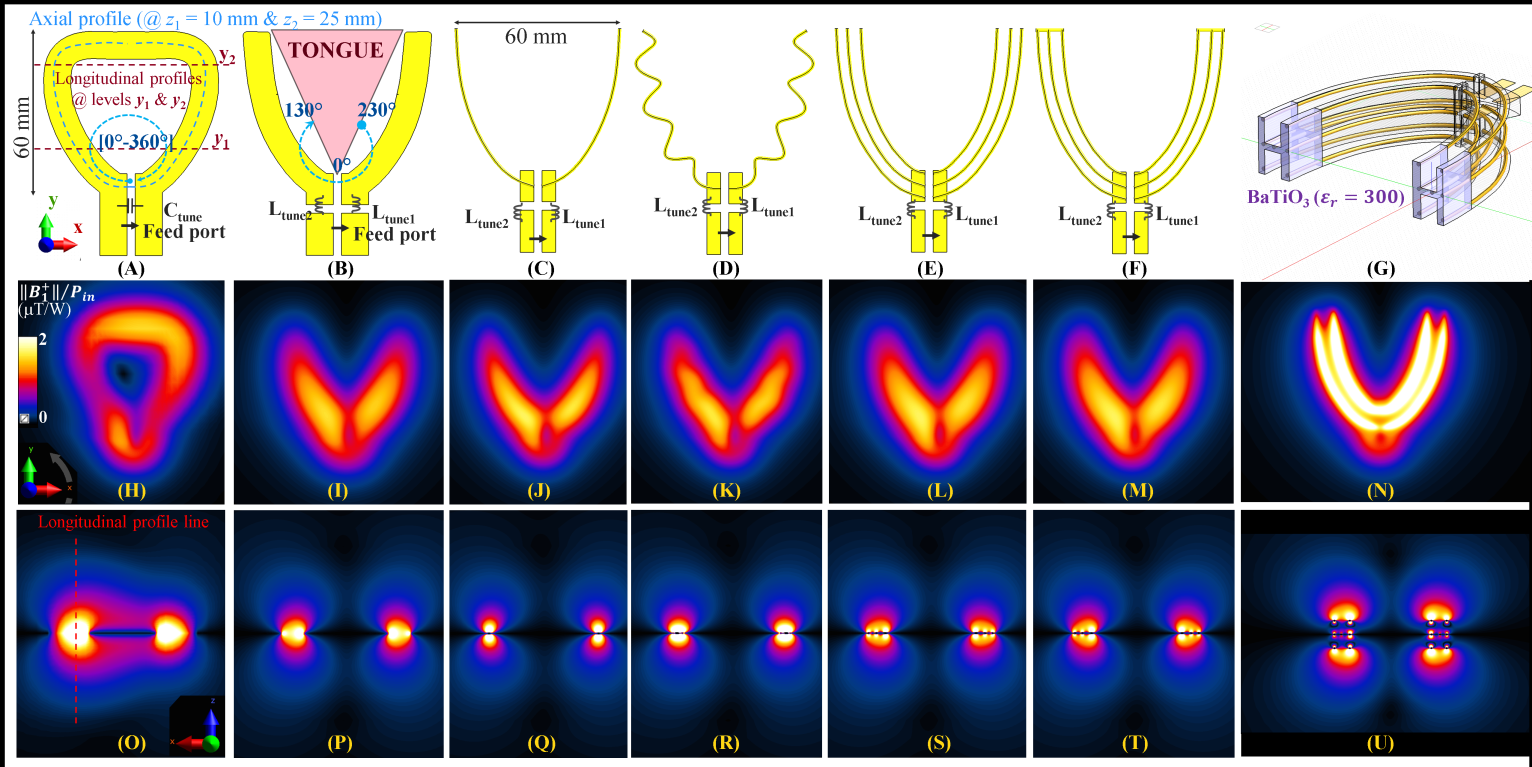
Fig. 1. Comparison of the intraoral coils. (A)
Reference loop coil model with the line profile tracks and levels marked.
Planar dipole models with (B) ribbon arms, (C) wire arms, (D) meander wire
arms, (E) 3-wire arms, (F) 3-wire arms with shorted ends, and (G) 7-wire dipole
with high-εr cap. Field maps are shown in the
same columns. (H)-(N) Sensitivity within the tongue region is
lower in dipoles compared to the loop coil. (O)-(U) Ribbon and multi-wire
conductors have better sensitivity across the dipole arms. High-permittivity cap increases transmit efficiency
and homogeneity.
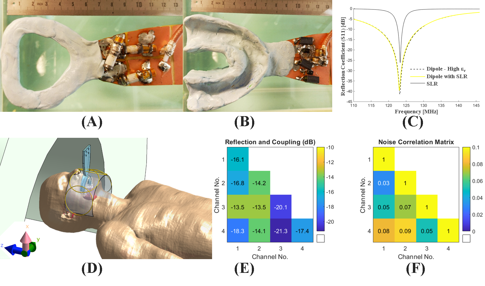
Fig.
2. Line profile comparison along the
dipole arm for different lengths of the high-permittivity cap at the end of the
multi-planar 7-wire dipole arm shows that the field homogeneity along the
dipole arm can be improved by adjusting the length of the high-permittivity cap.
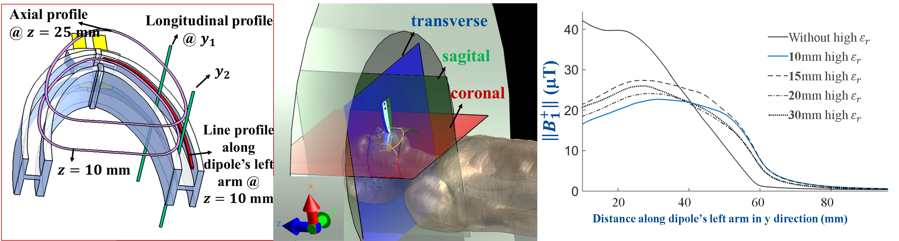
Fig.
3. A photo of A) the reference loop
coil, B) 7-wire dipole with shorted ends and high εr cap (not visible), and C) the S-parameter
measurements. D) An illustration of the coil positioning for dipole combined
with SLR array, E) S-parameter and F) Noise correlation matrices of the SLR
array.
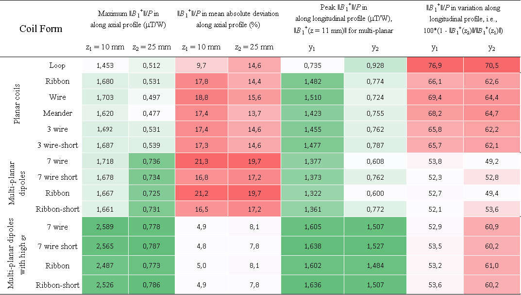
TABLE I.
Results of the line profile comparison for
simulations of 13 dipole antenna designs and the reference loop coil design.
Values that represent the intensity are color-coded with green, whereas the
inhomogeneity, i.e., deviation of the intensity, is rated with red color scale.
The columns are grouped into two for color coding.
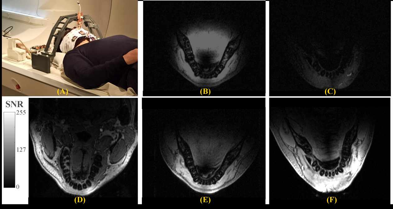
Fig.
4. A photo of the in vivo measurement setup. SNR maps at z = 10mm
away from the coil planes for intraoral B) loop, C) dipole, D) extraoral SLR
only, and SLR combined with E) loop and F) dipole in Tx mode. The image
intensities are scaled to the same range to allow a visual SNR comparison. SLR
combined with the intraoral dipole provides higher SNR and less signal from the
central region of the tongue.