0130
Unshielded Bent Folded-End Dipole 9.4 T Human Head Transceiver Array Decoupled Using Modified Passive Dipoles.
Nikolai Avdievich1, Georgiy Solomakha2, Loreen Ruhm1, Anke Henning1,3, and Klaus Scheffler1
1High-field Magnetic Resonance, Max Planck Institute for Bilogical Cybernetics, Tübingen, Germany, 2Physics and Engineering, ITMO University, St. Petersburg, Russian Federation, 3Advanced Imaging Research Center, University of Texas Southwestern Medical Center, Dallas, TX, United States
1High-field Magnetic Resonance, Max Planck Institute for Bilogical Cybernetics, Tübingen, Germany, 2Physics and Engineering, ITMO University, St. Petersburg, Russian Federation, 3Advanced Imaging Research Center, University of Texas Southwestern Medical Center, Dallas, TX, United States
Synopsis
Dipole antennas have been used for human imaging at ultra-high field (UHF, >7T). However, for head imaging, dipoles must be substantially shortened, which often cause poor (~ -10dB) decoupling. Common decoupling methods are difficult to use due to distant location of dipoles. Alternatively, adjacent transmit dipoles can be decoupled using passive dipole antennas placed parallel between them. Such passive dipoles may interact destructively with the RF field of the transmit array. In this work, we developed a novel decoupling method of adjacent transmit dipoles by using modified perpendicular passive dipole antennas. The constructed array demonstrated good decoupling and whole-brain coverage.
Purpose
To develop an unshielded transceiver (TxRx) folded-end dipole array for human head imaging at 9.4T and improve decoupling of adjacent dipole elements, a novel array design with modified passive dipole antennas was developed, evaluated, and tested.Introduction
Dipole antennas have recently been introduced (1) and used for human body imaging (1-3) at ultra-high field (UHF, >7T). For head imaging, dipoles must be substantially shortened (4-7). Such short dipoles are often decoupled only to the level of ~-10dB (4,7), which is insufficient for optimal transmit (Tx) performance. Common decoupling methods, which require electrical connections, are difficult to use for decoupling of distantly located adjacent Tx-dipoles. Alternatively, adjacent dipoles can be decoupled using passive dipole antennas placed between them (5,8). This decoupling practice should be used with care since passive dipoles may interact destructively with the RF-field, B1+, produced by the Tx-array (9). In this work, we developed a novel decoupling method of adjacent Tx-dipoles by using modified passive dipole antennas.Methods
The general idea behind the folded-end dipole design is shown in Fig.1A. Commonly, the resonance frequency of a short dipole antenna is decreased by connecting inductors in series. In such design, we “cut out” the central part of the dipole current and voltage distributions, which is “hidden” within the inductors. As a result, the “loaded” portion of the distribution has large voltage values at both ends and a very non-uniform current distribution. Alternatively, by folding the dipole (Fig.1B), we load only its central portion, which has lower voltage values and a more uniform current. Coupling between two Tx-dipole antennas produces two modes (Fig.1C). The anti-parallel mode creates no RF field in the center between the dipoles. Thus, a parallel passive decoupling dipole (Fig.1D, top) interacts only with the parallel mode. Therefore, such passive dipole resonating higher than both modes can shift down only the frequency of the parallel mode, which is adjusted by varying the passive dipole resonance frequency. Degeneracy of the two modes corresponds to decoupling of the Tx-dipoles. To minimize destructive interaction, we turned the passive dipole by 90º (Fig.1D, bottom) and bent to increase coupling with the Tx-dipoles. Such passive dipole interacts only with the anti-parallel mode. By varying the passive dipole resonance frequency, which is now lower than that of both modes, the resonance frequency of the anti-parallel mode can be shifted up. Degeneracy of the two modes corresponds to decoupling of the Tx-dipoles.Electromagnetic simulations were performed using CST Studio Suite 2019 (CST, Darmstadt, Germany) and the time-domain solver based on the finite-integration technique. We simulated several 8-element dipole arrays (folded-end and unfolded) decoupled using parallel and perpendicular passive decoupling dipoles (Fig.2). After modeling, we constructed an 8-element transceiver unshielded dipole array decoupled using novel perpendicular passive dipoles (Fig.3B). The array measured 200mm in width, 230mm in height, and 170mm in length. To increase B1+ field at the superior head locationad (10), we added a flat elliptical RF shield (Fig.3A). All data were acquired on a Siemens Magnetom 9.4T human imaging system.
Results and Discussion
The array was well decoupled (Fig.3D). All adjacent elements of the array were decoupled better than -15dB with an average S12 value of -18.1dB. Figs.2C,D show simulated transversal B1+ maps and their ratios obtained using decoupled folded-end dipole arrays. Parallel passive dipoles produce a strong destructive interference with the B1+ field both at the periphery and the center of the phantom where the field is reduced by 16%. Turning the passive dipoles by 90º substantially minimizes the alteration of the RF-field both at the periphery and center (3% reduction). Similar results were obtained for decoupling of the unfolded dipole array (Fig.2B). Fig.4 displays sagittal B1+ and transversal SAR10g maps obtained using different 1x8 dipole arrays loaded by a head voxel model. Increasing the fold size, which makes the current distribution along the dipole more uniform (Fig.1B), extends the RF-field in both directions and ~1.5 times decreases the peak SAR10g (slice 2, ears). SAR10g maps through the array center (slice 1) are very similar. Optimal 30-mm bent folded-end dipole array also produced higher B1+/√P (7%) and B1+/√pSAR10g (~30%) than the unfolded array. Fig.5 shows in-vivo experimental data. The unshielded folded-end dipole array provided good coverage over the entire brain. Averaged over a 130-mm transversal slab, B1+ measures 9.3 μT/√kW.Conclusion
We developed a novel passive dipole design for decoupling transmit human head dipole arrays. The new perpendicular decoupling antennas produced substantially less destructive interference with the RF-field of the array than the common parallel design. The constructed eight-element dipole array demonstrated good decoupling and whole-brain coverage.Acknowledgements
Funding by the ERC Starting grant / SYNAPLAST / 679927 and the Cancer Prevention and Research Institute of Texas (CPRIT) grant / RR180056 is kindly acknowledged.References
1) Raaijmakers AJE, Ipek O, Klomp DWJ et al. Magn Reson Med 2011;66:1488-1497. 2) Oezerdem C., Winter L., Graessl A. et al. Magn Reson Med 2016;75:2553–2565. 3) Raaijmakers AJE, Italiaander M, Voogt IJ et al. Magn Reson Med 2016;75:1366–1374. 4) Chen G, Cloos M, Sodickson D, and Wiggins G. Proc. ISMRM 2014, p.621. 5) Clément J, Gruetter R, and Ipek Ö. Magn Reson Med 2019;81:1447–1458. 6) Connell IRO, Mennon RS IEEE Trans Med Imag 2019;38: 2177-2187. 7) Avdievich NI, Solomakha G, Ruhm L, Scheffler K, Henning A. NMR in BioMed 2020;33:1-11. 8) Yan X, Zhang X, Wei L, Xue R. Appl Magn Res 2015;46:59-66. 9) Avdievich NI, Pan JW, and Hetherington HP. NMR in Biomed 2013;26(11):1547-1554. 10) Alecci M, Collins CM, James Wilson J, Liu W, Smith MB, Jezzard P. Magn Reson Med 2003;49:363-370.Figures
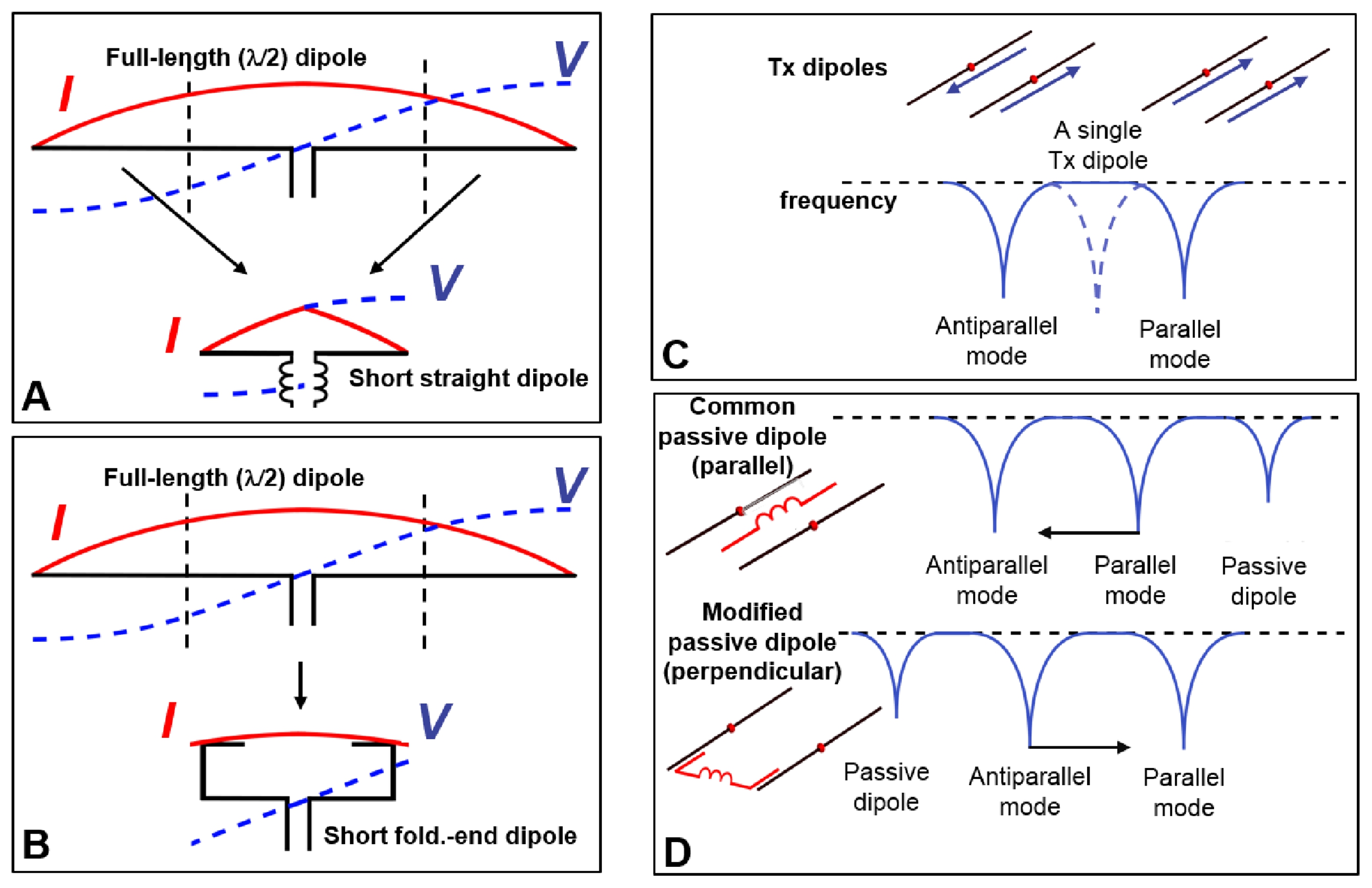
Figure 1. A) Current and voltage
distributions along the length of the full-length dipole vs a “short” dipole.
B) Current and voltage distributions along the length of a folded-end dipole.
C) Two modes of a pair of coupled dipole antennas. Dashed curve shows the
resonance line of a single dipole. D) General representation of the decoupling
effect produced by an addition of the common straight parallel (top) and
modified perpendicular (bottom) passive dipoles both shown in red. To increase
the electrical length, both passive dipoles have a lumped-element inductor
connected in series.
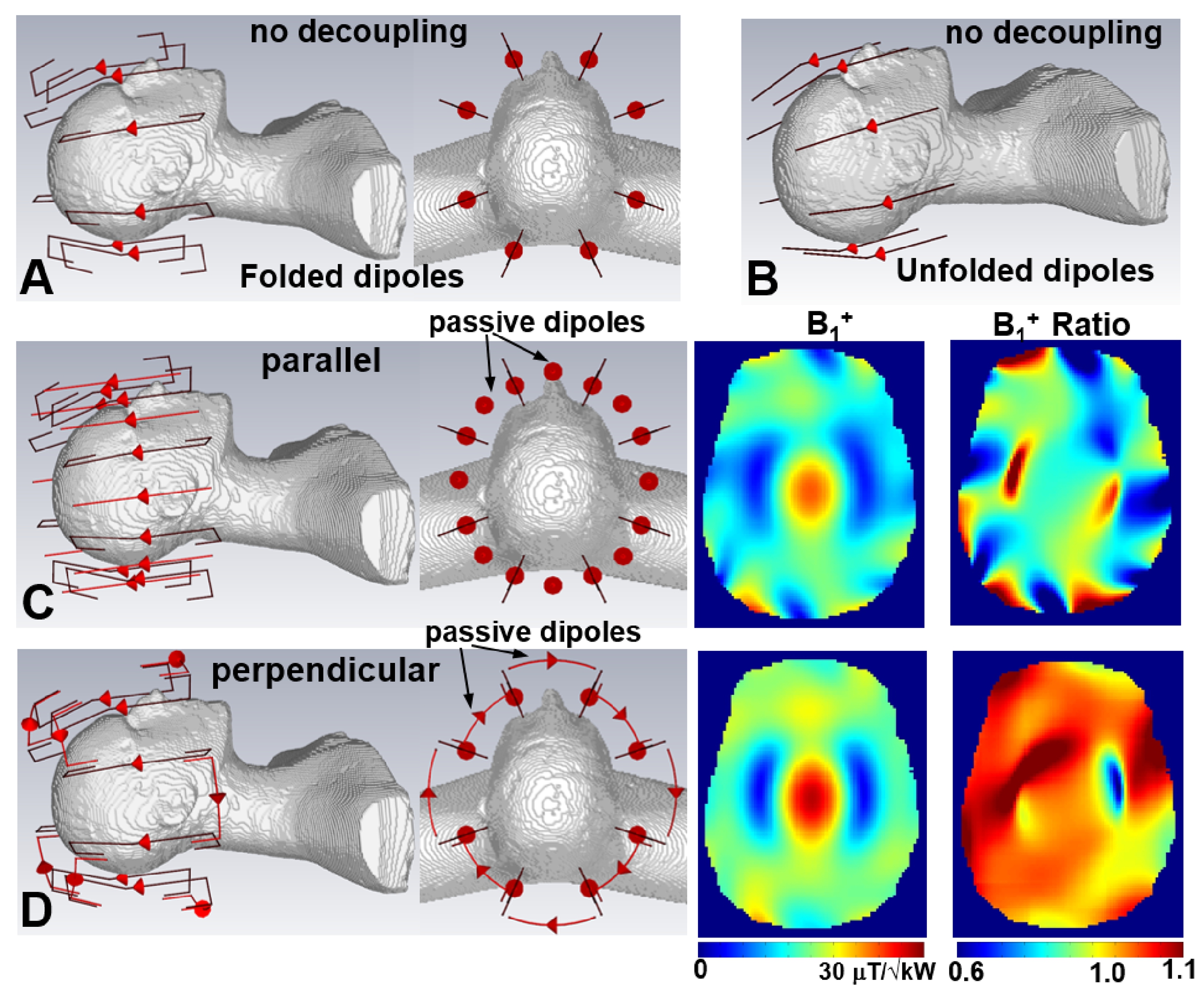
Figure 2. CST simulation models of the folded-end (A) and unfolded (B) dipole
arrays without decoupling. CST simulation models and results (B1+, B1+
ratio) for 1x8 bent folded-end dipole arrays decoupled using the common
parallel dipoles (C) and modified perpendicular dipoles (D). All arrays are
loaded by the head and shoulder (HS) phantom. Transmit dipoles and passive
dipoles are shown in black and red, respectively. B1+
ratio is calculated by dividing corresponding B1+ maps by
one obtained using the array without decoupling (Fig.2A).
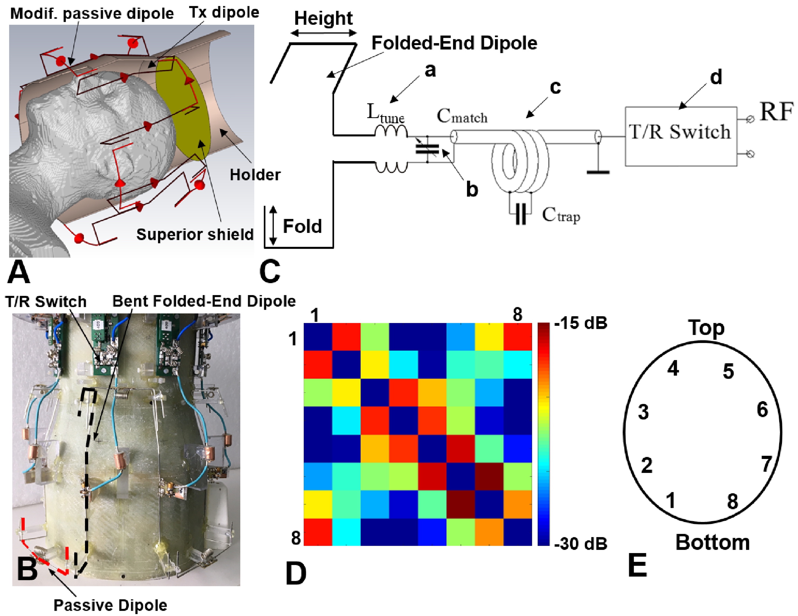
Figure
3. A) EM simulation model of the 1x8 30-mm bent folded-end dipole array. B)
Photo of the dipole array with the cover and RF shield removed. An exemplary
transmit dipole and passive decoupling dipole are marked by a black
and red dash lines, respectively. C) Schematic of a single folded-end dipole
element including tuning inductors (a), matching capacitor (b), the cable trap
(c), and the T/R switch unit (d). D) S12
matrix measured for the 8-element bent folded-end dipole array loaded by the HS
phantom. Highest S12 value did not exceed -15dB. E)
Numeration of the dipole elements.
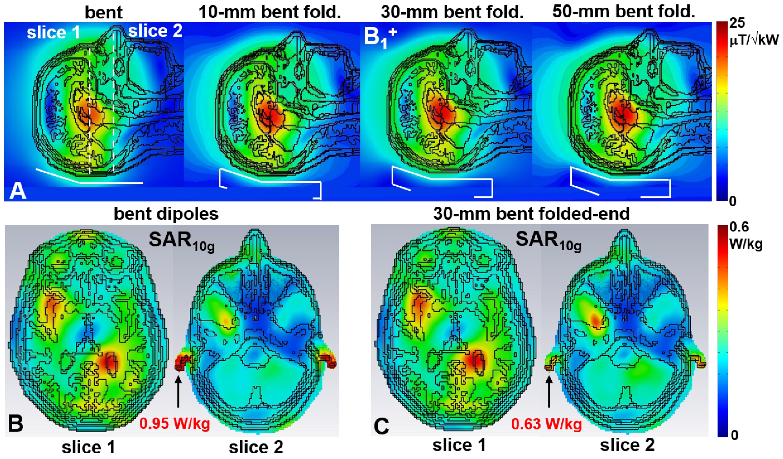
Figure
4. A) EM Simulated central sagittal B1+ maps
obtained using different dipole arrays loaded by a human head (“Duke”) voxel
model. Single elements of corresponding dipole arrays are shown in Figure 4A in
white. Transversal SAR10g maps obtained for two slices using the 1x8
bent dipole array (B) and 30-mm bent folded-end dipole array (C). Positions of
both slices are shown in Figure 4A.
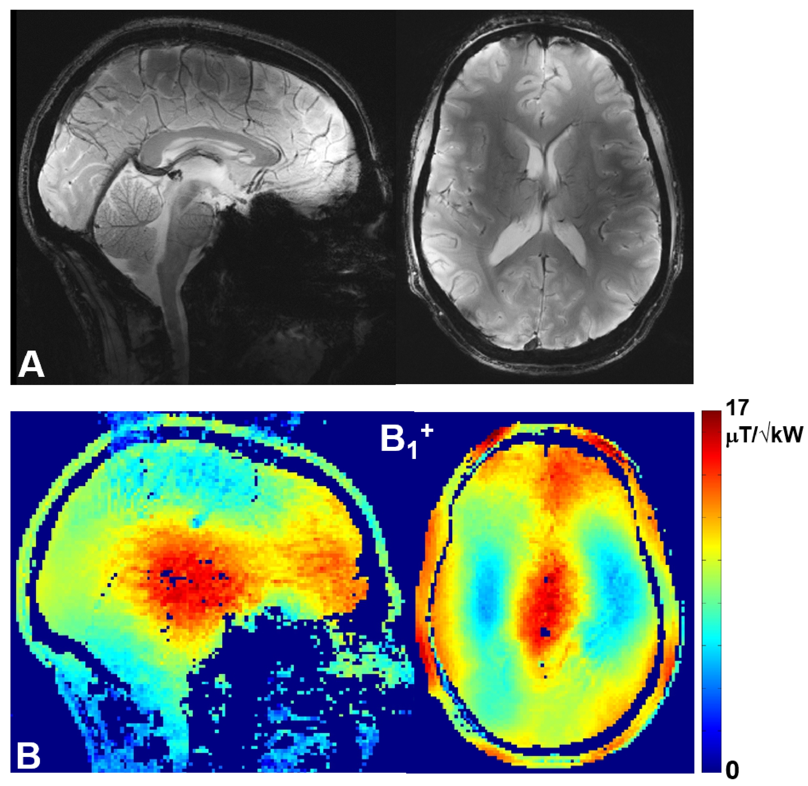
Figure
5. A) Central sagittal and transversal in-vivo human brain GRE images (A) and
corresponding B1+ maps (B) obtained for a male
subject.