S57
Impact of Reformatting Brain PET Images to the AC-PC line of MR images
Vahid Ravanfar1, Mohammad Mehdi Khalighi2, Chad Bobb3, Namasvi Jariwala1, Edgar Castellanos Diaz1, Emma Bahroos1, and Javier Villanueva-Meyer1
1Radiology, UCSF, San Francisco, CA, United States, 2Stanford University, Palo Alto, CA, United States, 3PET/MR Engineering, GE Healthcare, Waukesha, WI, United States
1Radiology, UCSF, San Francisco, CA, United States, 2Stanford University, Palo Alto, CA, United States, 3PET/MR Engineering, GE Healthcare, Waukesha, WI, United States
Synopsis
When PET images are fused to MR images which are aligned to the Talairach anterior commissure (AC) – posterior commissure(PC) line, the PET images are reformatted to the AC-PC plane. The reformatting of the PET images may change the visual appearance of a tumor based on the axial slice angle of the fused images. When reading PET/MR images, one must note the displayed plane of PET images as compared to the MR images. Cross-referencing between PET and MR should be performed on images displayed in the same plane.
BACKGROUND
Both Positron Emission Tomography (PET) and Magnetic Resonance Imaging (MRI) have revolutionized the world of diagnostic imaging. Furthermore, the fusion of these modalities has allowed for a more complete test within diagnostic imaging of multiple diseases including brain cancer [1]. The high spatial resolution and soft tissue contrast of MR images enables favorably accurate co-localization of high uptake lesions on PET images. In order to do so, the PET and MR images are commonly fused together by overlaying a colored PET image on the corresponding gray-scale MR image.When acquiring PET/MRI images for a brain scan on a simultaneous PET/MRI scanner (SIGNA, GE Healthcare, Waukesha, WI) [2], it is standard practice to acquire axial MR images using the Talairach anterior commissure (AC) – posterior commissure (PC) line as the reference plane. The MR axial slice plane is defined based on how the patient’s head is positioned within the MR head coil. This position varies from patient to patient and can be extreme when imaging kyphotic patients. PET reconstruction is inherently 3D with full volume reconstruction whereby axial slices are determined by the PET ring around the patient and not a prescribed acquisition plane like MR. Therefore, since the axial PET and MR images are acquired on different planes, and MR images often become blurred when reformatted due to the slice thickness, the PET images should be reformatted to the MR acquisition plane for image review and fusion.
When PET images are fused to MR images which are aligned to the AC-PC line, the PET images are reformatted to the AC-PC plane. The reformatting of the PET images may change the visual appearance of a tumor based on the axial slice angle of the fused images. Caution should be taken at interpretation and particularly if one is taking measurements on the straight axial PET images as the fused images are not on the straight axial plane and may not represent the same 3D space.
TEACHING POINT
Three patients were scanned twice using two distinct different angles. The first scan demonstrates the angle through the Anterior Commissure (AC) – Posterior commissure (PC) line (Figure 1). The second scan depicts a straight axial image (Figure 2). The images demonstrate the difference between the reformat of PET images to the AC/PC plane which is typically used in routine radiological practice as compared to the straight axial plane which is normally read by nuclear physicians. Technologists should take note of this distinction as hybrid PET/MR scanners enter increased clinical use.SUMMARY
When reading PET/MR images, one must note the displayed plane of PET images as compared to the MR images. Cross-referencing between PET and MR should be performed on images displayed in the same plane.Acknowledgements
We would like to thank Sharmila Majumdar, PhD. for her guidance and support on this project.References
- Gaertner FC, Fürst S, and Schwaiger M, “PET/MR: a paradigm shift,” Cancer Imaging. 2013; 13(1): 36-52.
- Levin CS et al., “Design features and mutual compatibility studies of the time-of-flight PET capable GE SIGNA PET/MR system,” IEEE transactions on medical imaging 35 (8), 1907-1914.
- M.F.Reiser,et al., PET-CT and PET-MRI in Oncology: A Practical Guide.(2012) DOI:10.007/978-3-642-01139-9.
- Andrea Ciarmiello, et al., PET-CT and PET-MRI in neurology: SWOT analysis applied to hybrid imaging. (2016) DOI:10.1007/978-3-319-31614-7.
Figures
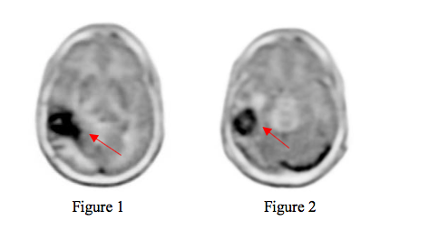
- Figure 1: The angle through the Anterior Commissure – Posterior commissure line (image volume).
- Figure 2 depicts a straight angle of 180 degrees.