S115
Building an MRI RF Coil for the Technologist
Rene Jack Roy1
1UVA, charlottesville, VA, United States
1UVA, charlottesville, VA, United States
Synopsis
The complexity and costs of MRI RF coil design seems out of reach for most non-physicists in the medical research field. To facilitate learning more about coil design and functionality, we have attempted to build a simple loop coil that can be used in small animal research.
Purpose
MR Imaging relies on the use of RF resonator coils or probes, to transmit radio-frequencies within the range of the imaging sample at a given magnetic field and in-turn collect signal back from the sample at the appropriate time during imaging. With the costs of commercially available coils ranging from 3000 US dollars to over a quarter of a million dollars, is it feasible for a technologist to build a simple loop coil, with a few select electrical components, that can be used for MR Imaging in a non-clinical setting?Methods
A simple loop transmit and receive coil will require three components: a loop of copper wire, three adjustable capacitors and a connection (BNC) to the MRI system. A capacitance meter and a RF Sweeper are used for both capacitor selection and for tuning of our coil and will assist in helping our project to succeed. The loop of wire is designed for both the size of the sample we will be imaging and the thickness of the wire. The Capacitors are glass, adjustable capacitors that we can install in parallel on the wire loop, one on each end of the loop for tuning each side, and one installed across the loop for balancing of the coil. Each capacitor has a range that can be adjusted for our needs. Static capacitors can be added to adjust the total capacitance of the coil to the desired frequency (300.4MhZ in this case). For our project, we will be using just the loop of wire and the three adjustable capacitors. A small circuit board was used to mount all of the hardware for stability and location of soldering points. It is very important to keep excessive solder from being a part of our coil.Results
We tested and tuned our coil on the Morris Frequency Response Sweeper (Morris Instruments Inc. Ottawa, Ont., Canada) and found that there was multiple resonance frequency within a small range of our needed frequency at 7 Tesla. After trial and error, we were able to get an adequate frequency at 300.4 MHz. The first MRI image was acquired on a 7T Bruker Clinscan small animal MRI system (Ettlingen, Germany) of a tomato to see what signal-to-noise we could acquire with the new probe. The gradient echo image was adequate for demonstrating structure with the tomato. T2 weighted images were then acquired along with T1 weighted images. Most of the images showed adequate SNR as compared to other commercially available RF coils of this size in our lab, but lacked the uniformity of signal across the imaging plane.Conclusion
It was demonstrated that a very simple MRI RF Coil could be constructed with just a few components in our lab by a non-physics technologist. Other coils have been attempted with some success and some failures. A Helmholtz Coil and a Saddle Coil were developed next, each with their own hurdles. More intricate probe design increases the complexity of tuning and balancing of the coil for optimal signal to noise. More sophisticated equipment and knowledge is needed if other, more advanced coil building is attempted.Acknowledgements
University of Virginia & Dr. Stuart Berr & Edwin BaldelomarReferences
No reference found.Figures
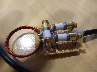
Loop Coil
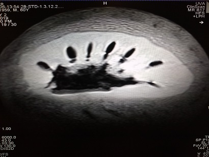
T2 Weighted image of a tomato