RF Modelling
1Department of Radiology, Weill Cornell Medicine, New York, NY, United States
Synopsis
In recent years, there is increasing interest to move MRI toward higher static field strengths. The motivation for higher field strengths lies in the promise of higher signal-to-noise ratio (SNR), however, higher field (e.g., 7 Tesla [T]) human MRI remains challenging due to several difficulties including the inhomogeneity of the transmitted radio frequency (RF) field, which leads to two phenomena.
- (1) Non-uniform excitation (B1+) and therefore non-uniform image intensity;
- (2) Non-uniform electric fields and therefore locally increased tissue heating.
This talk will focus on RF modeling methods to predict B1+ and SAR distributions in the human body.
INTRODUCTION
In recent years, there is increasing interest to move MRI toward higher static field strengths. The motivation for higher field strengths lies in the promise of higher signal-to-noise ratio (SNR), however, higher field (e.g., 7 Tesla [T]) human MRI remains challenging due to several difficulties including the inhomogeneity of the transmitted radio frequency (RF) field, which leads to two phenomena distinctly related to UHF MRI. (1) Non-uniform excitation (B1+) and therefore non-uniform image intensity; (2) Non-uniform electric fields and therefore potential hotspots and locally increased tissue heating.NON-UNIFORM TRANSMIT FIELDS (B1+)
Even at moderately high field strengths such as 3T, B1+ inhomogeneity effects are observed and are severe enough in certain applications to warrant detailed understanding and correction—this is especially important at 3T given the clinical importance of this field strength [1]. In the case of 3T breast MR, this B1+ nonuniformity results in a distinct left–right asymmetry, such that the B1+ field magnitude in the left breast is increased by a factor of approximately 1.3 with regard to the right breast for various patient orientations and types of body coils [2]-[3]. An example of the B1+ distribution is shown in Figure 1a, with another example in Figure 1b showcasing the MR image shading that results from such an inhomogeneous B1+ distribution.The aforementioned problems of B1+ nonuniformity arise as a result of loading of the body coil (Fig. 1c) by the human body. As shown in Figure 1f, the polarization distribution of the B1 field becomes severely perturbed compared with the circularly polarized unloaded B1 field in Figure 1e, even at the moderate field strength of 3T as shown here. This results in a generally noncircular (elliptical) polarization, with certain regions that even degenerate into a linear polarization. In practice, this translates into a smaller left-hand rotating component of the transmitted B1+-field, with the remaining portion of the total B1-field spilling over into the right-hand polarization (i.e., the B1 component of the transmit field), which is not useful for spin excitation—the result is a lower efficiency for spin excitation as well as a decreased receive RF signal in certain areas of the image, leading to local image shading.
NON-UNIFORM TISSUE HEATING (SAR)
This safety issue is one of the most important limiting factors in the design and use of the RF components for UHF MRI, since there is a risk of patient injury through the deposition of high RF power levels within small regions (“hotspots”) for extended times, leading to local heating with potential tissue damage. The key parameter used in characterizing MR safety for RF coils is the specific absorption rate (SAR), which measures the power delivered to a certain mass of tissue in W/kg. Current technology is not equipped to measure SAR locally; the only quantity that can be easily determined in-vivo is the overall average, or global, SAR, which is a measure of the average power absorbed per unit mass of tissue that is delivered to the entire mass of the body part under investigation (e.g. head or torso). In UHF MRI, higher static field strengths result in higher global specific absorption rate (SAR) values. Additionally, the wave phenomena that emerge in UHF MRI introduce an inherent spatial variation of the electric fields, resulting in a spatially-varying local SAR pattern (Figure 2). The local variation is hard to predict due to anatomical, tissue compositional and positional variations between patients, as well as variations determined by the transmit RF coil. This increased and difficult to predict local SAR may in fact be the dominant limitation of high field and especially UHF MRI.Parallel transmit (pTx) technology, in which multiple transmit RF channels can be controlled independently [4],[5], has become popular for mitigating the B1+ field non-uniformity problems that occur at higher field strengths. However, an unconstrained combination of the power output of multiple channels can, in a worst-case scenario, causes very strong local heating effects due to constructive interference of the electric field components from each channel, leading to strong local SAR hotspots, possibly even stronger than those produced by conventional excitation. This concern has led to the development of SAR-aware pTx methods, which employ knowledge of E-fields in addition to the extra degrees of freedom provided by the multi-transmit coil, to reduce local SAR hotspots while simultaneously constraining B1+ inhomogeneity [6]-[11]. To date there is still no good method available to directly and non-invasively measure local SAR in-vivo. In the current practical environment the global or average SAR is measured and a conservative estimate of the peak local SAR is established using a ratio that is typically in the range between 3:1 and 20:1 [12]. The peak local SAR can then be estimated from the measured global SAR by multiplication with this ratio.
RF MODELING
Electromagnetic and RF modeling has become a popular tool to assess B1+ and SAR in simulation [13]-[16]. A diverse family of detailed body models can be used to estimate B1+, global SAR, and peak local SAR in various different body types ranging from infants to adults of different gender. While B1+ and SAR values can still vary from patient to patient, with patient position, and with other variables, these simulations provide a strong basis for novel approaches that tackle B1+ and SAR prediction more accurately [17]-[20]. Given the strong incentive to develop UHF MRI into a clinical tool, it is paramount to find a viable and accurate method for monitoring the spatially varying SAR pattern, and therefore the actual ratio of peak local SAR to global SAR, as the key parameter in MRI safety. This talk will focus on the simulation methods available today for use in MRI B1+ and RF heating safety assessment.Acknowledgements
No acknowledgement found.References
[1] Rakow-Penner R, Hargreaves BA, Glover G, Daniel BL. Breast MRI at 3T. Appl Radiol. 2009;38:6–13.
[2] Sung K, Daniel BL, Hargreaves BA. Transmit B1+ field inhomogeneity and T1 estimation errors in breast DCE-MRI at 3 tesla. J Magn Reson Imaging. 2013;38:454–459.
[3] Winkler SA, Rutt BK. Practical methods for improved B1+-homogeneity in 3T breast imaging. J Magn Reson Imaging. 2015 Apr;41(4):992-9. doi: 10.1002/jmri.24635. Epub 2014 Apr 10.
[4] Zhu Y. 2004. Parallel excitation with an array of transmit coils. Magn Reson Med 51(4):775-84.
[5] Katscher U, Börnert P, Leussler C, van den Brink JS. 2003. Transmit SENSE. Magn Reson Med 49(1):144-50.
[6] Martin A, Schiavi E, Eryaman Y, Herraiz JL, Gagoski B, Adalsteinsson E, Wald LL, Guerin B. 2016. Parallel transmission pulse design with explicit control for the specific absorption rate in the presence of radiofrequency errors. Magn Reson Med 75(6):2493-504.
[7] Graesslin I, Vernickel P, Börnert P, Nehrke K, Mens G, Harvey P, Katscher U. 2015. Comprehensive RF safety concept for parallel transmission MR. Magn Reson Med 74(2):589-98.
[8] Guérin B, Setsompop K, Ye H, Poser BA, Stenger AV, Wald LL. 2015. Design of parallel transmission pulses for simultaneous multislice with explicit control for peak power and local specific absorption rate. Magn Reson Med 73(5):1946-53.
[9] Guérin B, Gebhardt M, Cauley S, Adalsteinsson E, Wald LL. 2014. Local specific absorption rate (SAR), global SAR, transmitter power, and excitation accuracy trade-offs in low flip-angle parallel transmit pulse design. Magn Reson Med 71(4):1446-57.
[10] Pendse M, Rutt BK. 2015. IMPULSE: A Generalized and Scalable Algorithm for Joint Design of Minimum SAR Parallel Transmit RF Pulses. Proc Int Soc Magn Res 23:0543.
[11] Seifert F, Wübbeler G, Junge S, Ittermann B, Rinneberg H. 2007. Patient safety concept for multichannel transmit coils. J Magn Reson Imaging 26(5):1315-21.
[12] IEC 60601-2-33
[13] Vaughan JT, Snyder CJ, DelaBarre LJ, Bolan PJ, Tian J, Bolinger L, Adriany G, Andersen P, Strupp J, Ugurbil K. 2009. Whole-body imaging at 7T: preliminary results. Magn Reson Med (1):244-8.
[14] Hand JW, Lau RW, Lagendijk JJ, Ling J, Burl M, Young IR. 1999. Electromagnetic and thermal modeling of SAR and temperature fields in tissue due to an RF decoupling coil. Magn Reson Med 42(1):183-92.
[15] Gandhi OP, Chen XB. 1999. Specific absorption rates and induced current densities for an anatomy-based model of the human for exposure to time-varying magnetic fields of MRI. Magn Reson Med 41(4):816-23.
[16] Simunić D, Wach P, Renhart W, Stollberger R. 1996. Spatial distribution of high-frequency electromagnetic energy in human head during MRI: numerical results and measurements. IEEE Trans Biomed Eng 43(1):88-94.
[17] Neufeld E, Fuetterer M, Murbach M, Kuster N. 2015. Rapid method for thermal dose-based safety supervision during MR scans. Bioelectromagnetics 36(5):398-407.
[18] Pendse M, Stara R, Mehdi Khalighi M, Rutt B. IMPULSE : A scalable algorithm for design of minimum specific absorption rate parallel transmit RF pulses. Magn Reson Med. 2019 Apr;81(4):2808-2822.
[19] Winkler SA, Picot PA, Thornton MM, Rutt BK. Direct SAR mapping by thermoacoustic imaging: A feasibility study. Magn Reson Med. 2017 Oct;78(4):1599-1606.
[20] Dixit N, Stang PP, Pauly JM, Scott GC. Thermo-Acoustic Ultrasound for Detection of RF-Induced Device Lead Heating in MRI. IEEE Trans Med Imaging. 2018 Feb;37(2):536-546.
Figures
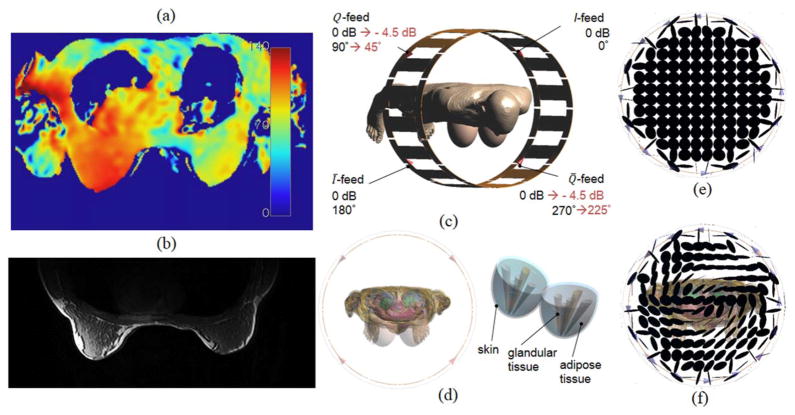
Figure 1
Example for the B1+ distribution (flip angle in degrees) (a) and the resulting image shading in the breast at 3T (b), obtained with a body coil. c: Computational model of a 3T body coil with body model (Virtual Family, Ella, 26 years, IT’IS foundation). d: Additional mammary tissue used for this modeling study. Polarization of the B1-field for unloaded body coil (e) and body coil loaded with body model (f).
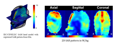
Figure 2
Example for the local SAR pattern observed in 7T brain MRI.