Basics of Transmission Lines & Power Transfer
1Perinatal Imaging and Health, King's College London, London, United Kingdom
Synopsis
The MRI signal is excited and detected using radiofrequency systems. To those unfamiliar with RF systems the equipment, concepts, and measurements can be intimidating and confusing. Developing an understanding of transmission lines, which form the basis for RF systems, allows one to easily understand most of the RF system at a basic level. The aim of this is to provide an introduction to transmission lines and the parameters/metrics commonly used with them. Additionally, some applications of transmission line theory to MRI will be introduced and discussed.
Target Audience
Those wishing to better understand RF systems in MRI by learning the fundamentals of transmission line theory as well as some common and novel applications of transmission line theory to MRI.Objective
The aim is to introduce and provide a fundamental understanding of the following concepts:- Transmission Line Theory
- Matching and Power Transfer
- Network Analysis
- The Smith Chart
- Common RF Circuits
- Applications of Transmission Line Theory in MRI
Transmission Line Basics, Impedance Matching, and Power Transfer
When the size of an electrical or electromagnetic circuit or structure begins to approach a significant fraction of the signal’s wavelength, it becomes necessary to account for the effect of the signal’s propagation when performing circuit and system analysis. This results in the development of transmission line theory which analyzes propagation of high-frequency signals. Transmission lines are characterized by their characteristic impedance – the ratio between voltage and current (or electric and magnetic fields) on the transmission line. In order to make interconnection between different components and systems easier, a characteristic impedance of 50Ω has been adopted as standard for most parts of the MRI system.Because RF signals are waves travelling on the transmission line structure, proper control of the characteristics and termination of the line is crucial to prevent reflection of power and ensure optimal transfer. Mismatch between the source, transmission line, and load can cause power loss and create standing waves which can also result in degradation of the received signal, equipment failure, and injury.
A number of impedance transformation techniques are available to match the impedances of amplifiers, coils, and other devices. Lumped elements such as capacitors and inductors are commonly used to match over limited bandwidths, and these can be replaced or complimented with transmission line structures. Broad-band matching can be accomplished using transformers and tapered impedance transformations.
A variety of transmission line structures can be commonly found in MRI systems, used for transferring signals as well as less obvious functions. Coaxial cables form the majority of interconnections in MRI systems, but other transmission line structures can also be found. Microstrip transmission lines can be used within subsystems and to construct RF coils, and the bore of the magnet frequently functions as a waveguide at 7T and above. Dielectric waveguides are also found in MRI, from fiber optic cables used for control and reception to the human body itself at ultra-high fields.
Network Analysis and The Smith Chart
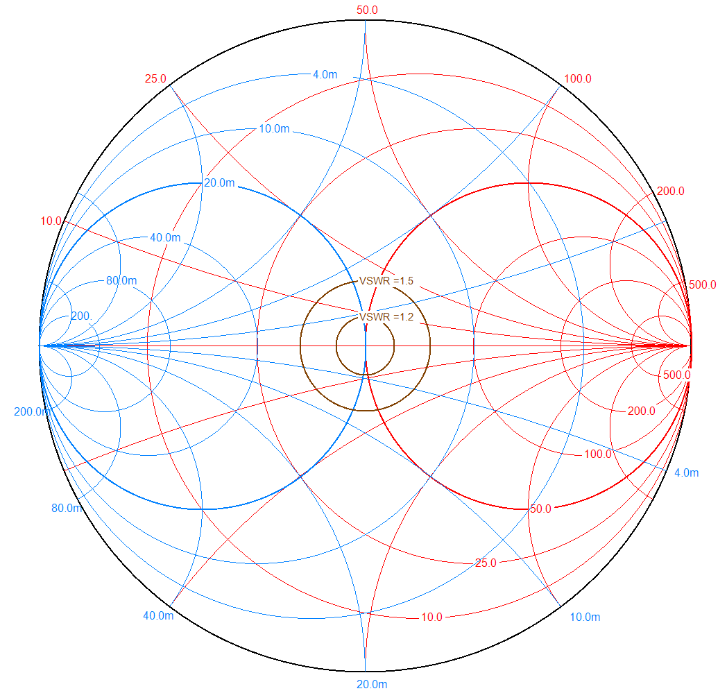
The characterization of RF transmission lines and circuits is accomplished by network analysis. There are a number of metrics used in the characterization of RF systems, but by far the most common are Scattering Parameters (S-Parameters), which characterize the magnitude and phase of power reflection and transmission. Other related parameters such as ABCD, Y, and Z matrices are often encountered in the design of systems and simulations of coils.An ingenious tool has been developed to both visualize the performance of RF circuits as well as perform calculations involving them. The Smith Chart (Figure 1) provides an intuitive way of visualizing the performance of RF circuits, and is especially helpful in the design and tuning of RF coils. Additionally, it can also be used to perform calculations of impedance transformations and matching networks.
Common RF Circuits
There are a few RF structures encountered frequently enough in MRI to merit specific discussion.- Directional couplers, which allow sampling of the signal travelling each direction on a transmission line, are frequently used as part of the transmit system to monitor power flow.
- Quadrature couplers, which divide a signal into two outputs with a 90° phase difference, are often used to transmit and receive from a quadrature transmit/receive coil.
- Baluns and cable traps serve to transform between single-ended and differential structures and block common-mode signals.
Applications to MRI
Transmission line theory finds use for more than just connecting together elements of the RF system. Uses and applications of transmission lines and related RF structures will be discussed to serve as examples of places these concepts and techniques can be applied. For example:- Some coils make use of transmission line concepts in their design or are formed from transmission lines.
- The impedance transforming properties of transmission lines can be used to replace lumped elements (especially inductors) with transmission line stubs in traps and matching networks.
- In addition to transforming impedances, transmission lines can be used to transform between voltages and currents. For example, this can be used to force elements of a transmit coil to have equal or proportional currents.
- The impedance or voltage transforming properties of transmission lines can be used to block common-mode signals (e.g. bazooka baluns) or transform single-ended sources to drive differential structures (e.g. half-wavelength 4:1 baluns).
Conclusion
Transmission lines are fundamental to the design and use of magnetic resonance systems. A basic understanding of transmission line theory and its implications will demystify the radiofrequency systems and structures used in MR and instruct on possible applications for RF technology.Acknowledgements
No acknowledgement found.References
Recommended Books:
D. M. Pozar, Microwave RF Engineering. 4th ed, John Wiley & Sons, Inc., New York, 2005.
R. E. Collin, Foundations for Microwave Engineering, 2nd ed. IEEE Wiley-Interscience, 2000
Figures