Applications of RF Pulse Designs: Inner Volume Imaging, SMS, B1 Shimming & pTx
1University of Glasgow, United Kingdom
Synopsis
This talk reviews a few popular RF pulse design applications: inner volume imaging, simultaneous multislice, $$$B_{1}$$$ shimming, and parallel transmission.
Target Audience
MRI scientists and pulse sequence developersOutcomes/Objectives
Following the educational talk on radio frequency (RF) pulse design theory, this talk will provide insight on a few interesting RF pulse applications:- Inner volume imaging: for higher resolution and/or accelerated imaging
- Simultaneous multislice (SMS) imaging: for accelerated imaging
- $$$B_{1}$$$ Shimming: for $$$B_{1}$$$ transmit field homogenization
- Parallel transmit: for homogenization of $$$B_{1}$$$, added degrees of freedom to pulse design, safer imaging at high fields, and much more!
Inner Volume Imaging
The imaging field of view (FOV) is often chosen to cover the extent of the body region being imaged and avoid FOV foldover aliasing, requiring finer sampling in data encoding k-space, $$$FOV=\frac{1}{\Delta k}$$$. This causes practical limitations to the temporal and spatial resolution achievable in some applications. When the goal is to image a smaller region within the body, inner volume (IV) excitation imaging is a tool to combat the need for higher resolution at faster speeds [1].One of the first IV techniques uses a pair of orthogonal, slab-selective RF pulses in a spin echo excitation and refocusing pair [1]. Only the rectangular volume that intersects the two planes is refocused into a spin echo, while everything else dephases. This later was named zonally magnified or "ZOOM" and incorporated a fast EPI readout [2,3]. Additional IV methods use spatially-selective 2D RF pulses [4-6] which in return incorporate 2D excitation trajectories such as EPI or spirals. Furthermore, fully tailored 3D volume excitations have been developed incorporating a variety of 3D trajectories [7-8].
Simultaneous Multislice
Simultaneous multislice (SMS) imaging, also known as multiband (MB) imaging is an effective means of accelerating imaging by exciting multiple slices separated by some distance. This reduces the total number of excitations required to obtain a full volume, with the speedup known as the MB factor. SMS is particularly useful for applications where speed is critical such as cardiac imaging, where a time series is collected such as fMRI and contrast enhanced MRI, and where acquisitions are long such as diffusion tensor imaging [9].Conventional SMS imaging operates on the principle of the Fourier shift theorem, where multiple slices are excited at different phases [10]. Summing these pulses creates a conventional multiband pulse:
$$b_{MB}(t)=A(t)\cdot\sum_{n=1}^{N}e^{i(\gamma G_{z}\cdot z_{n}\cdot t+\phi_{n})}$$
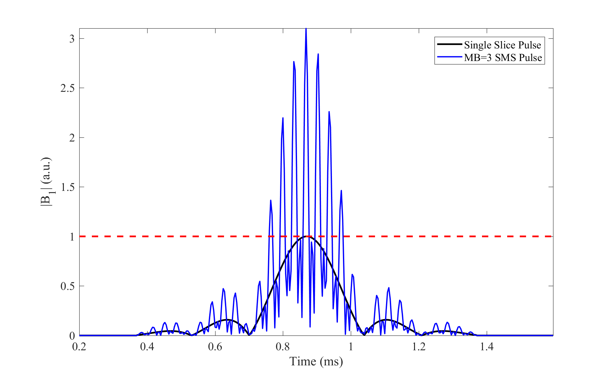
where $$$A(t)$$$ is the slice select envelope, $$$N$$$ is the MB factor, $$$\gamma$$$ is the gyromagnetic ratio, and $$$z_{n}$$$ is the slice position at each $$$n$$$th slice with phase offset $$$\phi_{n}$$$. $$$A(t)$$$ is typically a standard slice-selective RF pulse shape which can be a truncated sinc function or a Shinnar Le-Roux (SLR) pulse [11]. During excitation, a trapezoidal slice-select gradient with amplitude $$$G_{z}$$$ common to all simultaneous slices is played. Due to the summing of multiple RF waveforms, SMS is often limited by either the RF amplifier hardware or power deposition contributing to the specific absorption rate or SAR (shown in Figure 1). In general, both the power deposition and peak amplitude of SMS pulses scale roughly linearly with the number of slices [12]. In this section of the talk, I’ll discuss some methods that have been proposed to address SMS peak amplitude and power limitations to leverage the benefits of MB imaging [12-16].
$$$B_{1}$$$ Shimming
As the Larmor frequency increase with field strength, the sinusoidal RF wavelength decreases and leads to constructive and destructive interference of the $$$B_{1}$$$ field, creating flip angle inhomogeneity within larger body regions such as the torso or even head at ultra-high fields (UHF, ≥7 T) [17, 18]. To combat this problem, the idea of a spatially-varying $$$B_{1}$$$ field is proposed via multi-port excitations, more commonly known as parallel transmission (pTx) [19]. Analogous to parallel imaging with multiple receive channels, pTx has been described as "Transmit SENSE’" with multiple RF channels [20].$$$B_{1}$$$ shimming is the simplest form of pTx, where the amplitude and phase of each transmit channel is set independently. This creates a combined $$$B_{1}$$$ field,
$$b(\textbf{r},t)=b_{1}(t)\cdot\sum_{c=1}^{C}w_{c}s_{c}(\textbf{r})$$
where $$$b(\textbf{r},t)$$$ is the combined $$$B_{1}$$$ shimmed RF field, $$$b_{1}(t)$$$ is the complex RF waveform constant for all $$$C$$$ transmit channels, $$$w_{c}$$$ are the complex channel weights or "shims’", and $$$s_{c}(\textbf{r})$$$ are the single channel transmit RF field maps. Typically, $$$B_{1}$$$ shimming is optimized for flip angle homogeneity within a volume or slice of interest, although specific applications have led to the derivation of other optimization cost functions [21].
Parallel Transmit
From the equation for $$$B_{1}$$$ shimming above, we might notice that we can leverage additional degrees of freedom with parallel transmission by altering the RF waveform per transmit channel $$$b_{1,c}(t)$$$ ,$$b(\textbf{r},t)=\sum_{c=1}^{C}s_{c}(\textbf{r})\cdot b_{1,c}(t)$$
This spatially and time-varying form is known as "dynamic pTx", or simply "pTx" for short. Since pTx was first proposed nearly two decades ago, a wealth of innovative pulse design solutions have been developed. A few notable examples include iterative pTx design in the spatial domain [22], 2D slice-selective pTx with spokes trajectories [23, 24], 3D non-selective k-t points trajectories [25], and recently the calibration-free universal pulses [26].
Although pTx is most commonly associated with $$$B_{1}$$$ or flip angle homogeneity, it can also be used in the "Transmit SENSE’" fashion to allow for reduced sampling of excitation k-space, leading to shorter RF pulses [27]. Therefore, pTx can be beneficial for other pulse designs discussed in this talk such as SMS and inner volume imaging.
In single transmit MRI, the SAR delivered by an RF pulse is proportion to the integrated RF power, yet in the case of pTx the superimposed $$$B_{1}$$$ fields can yield local SAR hotspots [28]. In early days of pTx, local SAR was only evaluated with electromagnetic (EM) field simulations for each voxel of a tissue model, which is computationally limiting for pTx pulse design and scanner SAR monitoring. In 2011 the method of virtual observation points (VOPs) was presented by Eichfelder et al., which establishes a worst-case upper SAR bound to cluster various regions within an EM model [29]. VOPs are now commonly used for pTx pulse design optimizations and are integrated into the pTx SAR monitoring framework of modern scanners with pTx capability. Although local SAR hotspots can be an initial cause for concern, pTx can in fact be used to craft safer MRI scanning but creating implant-friendly imaging schemes [30, 31] or enabling sophisticated techniques such as dark mode imaging [32].
Acknowledgements
References
[1] D. A. Feinberg, J. C. Hoenninger, L. E. Crooks, L. Kaufman, J. C. Watts, and M. Arakawa, “Inner Volume MR Imaging: Technical Concepts and Their Application,” Radiol, vol. 156, pp. 743–747, Sep. 1985.
[2] P. Mansfield, R. J. Ordidge, and R. Coxon, “Zonally Magnified EPI in Real Time by NMR,” J. Phys. E: Sci. Instrum., vol. 21, no. 3, pp. 275–280, Mar. 1988, doi: 10.1088/0022-3735/21/3/008
[3] C. A. M. Wheeler-Kingshott et al., “ADC Mapping of the Human Optic Nerve: Increased Resolution, Coverage, and Reliability with CSF-Suppressed ZOOM-EPI,” MRM, vol. 47, no. 1, pp. 24–31, Jan. 2002, doi: 10.1002/mrm.10016.
[4] S. Rieseberg, J. Frahm, and J. Finsterbusch, “Two-Dimensional Spatially-Selective RF Excitation Pulses in Echo-Planar Imaging,” MRM, vol. 47, no. 6, pp. 1186–1193, Jun. 2002, doi: 10.1002/mrm.10157.
[5] D. Mitsouras, R. V. Mulkern, and F. J. Rybicki, “Strategies for Inner Volume 3D Fast Spin Echo Magnetic Resonance Imaging Using Nonselective Refocusing Radio Frequency Pulses,” Med. Phys., vol. 33, no. 1, pp. 173–186, Dec. 2005, doi: 10.1118/1.2148331.
[6] E. U. Saritas, C. H. Cunningham, J. H. Lee, E. T. Han, and D. G. Nishimura, “DWI of the Spinal Cord with Reduced FOV Single-Shot EPI,” MRM, vol. 60, no. 2, pp. 468–473, Aug. 2008, doi: 10.1002/mrm.21640.
[7] H. Sun, J. A. Fessler, D. C. Noll, and J.-F. Nielsen, “Rapid Inner-Volume Imaging in the Steady-State with 3D Selective Excitation and Small-Tip Fast Recovery Imaging,” MRM, vol. 76, no. 4, pp. 1217–1223, Oct. 2016, doi: 10.1002/mrm.26026.
[8] M. Davids, L. R. Schad, L. L. Wald, and B. Guérin, “Fast Three-Dimensional Inner Volume Excitations Using Parallel Transmission and Optimized K-space Trajectories,” MRM, vol. 76, no. 4, pp. 1170–1182, Oct. 2016, doi: 10.1002/mrm.26021.
[9] M. Barth, F. Breuer, P. J. Koopmans, D. G. Norris, and B. A. Poser, “Simultaneous Multislice (SMS) Imaging Techniques: SMS Imaging,” MRM, vol. 75, no. 1, pp. 63–81, Jan. 2016, doi: 10.1002/mrm.25897.
[10] S. Müller, “Multifrequency Selective RF Pulses for Multislice MR Imaging,” MRM, vol. 6, no. 3, pp. 364–371, Mar. 1988, doi: 10.1002/mrm.1910060315.
[11]J. M. Pauly, P. Le Roux, D. G. Nishimura, and A. Macovski, “Parameter Relations for the Shinnar-Le Roux Selective Excitation Pulse Design Algorithm,” IEEE TMI, vol. 10, no. 1, pp. 53–65, Mar. 1991, doi: 10.1109/42.75611.
[12] E. Wong, “Optimized Phase Schedules for Minimizing Peak RF Power in Simultaneous Multi-Slice RF Excitation Pulses,” in International Society of Magnetic Resonance in Medicine, Melbourne, Australia, 2012, p. 2209.
[13] D. G. Norris, P. J. Koopmans, R. Boyacioğlu, and M. Barth, “Power Independent of Number of Slices (PINS) Radiofrequency Pulses for Low-Power Simultaneous Multislice Excitation,” MRM, vol. 66, no. 5, pp. 1234–1240, Nov. 2011, doi: 10.1002/mrm.23152.
[14] A. Sharma, M. Lustig, and W. A. Grissom, “Root-Flipped Multiband Refocusing Pulses,” MRM, vol. 75, no. 1, pp. 227–237, Jan. 2016, doi: 10.1002/mrm.25629.
[15] S. N. Williams, J. A. Fessler, and D. C. Noll, “Minimum Out-of-Slice Error SMS RF Pulse Design with Direct Peak, Power, and In-Slice Error Constraints,” presented at the European Society for Magnetic Resonance in Medicine and Biology, Barcelona, Spain, Oct-2017.
[16] A. Rund, C. S. Aigner, K. Kunisch, and R. Stollberger, “Magnetic Resonance RF Pulse Design by Optimal Control With Physical Constraints,” IEEE TMI, vol. 37, no. 2, pp. 461–472, Feb. 2018, doi: 10.1109/TMI.2017.2758391.
[17] P. A. Bottomley and E. R. Andrew, “RF Magnetic Field Penetration, Phase Shift and Power Dissipation in Biological Tissue: Implications for NMR Imaging,” Phys Med Biol, vol. 23, no. 4, pp. 630–643, Jul. 1978, doi: 10.1088/0031-9155/23/4/006.
[18] T. S. Ibrahim, R. Lee, A. M. Abduljalil, B. A. Baertlein, and P.-M. L. Robitaille, “Dielectric Resonances and B1 Field Inhomogeneity in UHFMRI: Computational Analysis and Experimental Findings,” MRI, vol. 19, no. 2, pp. 219–226, Feb. 2001, doi: 10.1016/S0730-725X(01)00300-9.
[19] T. S. Ibrahim, R. Lee, B. A. Baertlein, A. Kangarlu, and P.-M. L. Robitaille, “Application of Finite Difference Time Domain Method for the Design of Birdcage RF Head Coils Using Multi-Port Excitations,” MRI, vol. 18, no. 6, pp. 733–742, Jul. 2000, doi: 10.1016/S0730-725X(00)00143-0.
[20] U. Katscher, P. Börnert, C. Leussler, and J. S. van den Brink, “Transmit SENSE,” MRM, vol. 49, no. 1, pp. 144–150, Jan. 2003, doi: 10.1002/mrm.10353.
[21] F. Padormo, A. Beqiri, J. V. Hajnal, and S. J. Malik, “Parallel Transmission for Ultrahigh-Field Imaging,” NMR in Biomedicine, vol. 29, no. 9, pp. 1145–1161, Sep. 2016, doi: 10.1002/nbm.3313.
[22] W. Grissom, C. Yip, Z. Zhang, V. A. Stenger, J. A. Fessler, and D. C. Noll, “Spatial Domain Method for the Design of RF Pulses in Multicoil Parallel Excitation,” MRM, vol. 56, no. 3, pp. 620–629, Sep. 2006, doi: 10.1002/mrm.20978.
[23] Z. Zhang, C.-Y. Yip, W. Grissom, D. C. Noll, F. E. Boada, and V. A. Stenger, “Reduction of Transmitter B1 Inhomogeneity with Transmit SENSE Slice-Select Pulses,” MRM, vol. 57, no. 5, pp. 842–847, May 2007, doi: 10.1002/mrm.21221.
[24] K. Setsompop et al., “Slice-Selective RF Pulses for In Vivo B 1+ Inhomogeneity Mitigation at 7 Tesla Using Parallel RF Excitation with a 16-Element Coil,” MRM, vol. 60, no. 6, pp. 1422–1432, Dec. 2008, doi: 10.1002/mrm.21739.
[25] M. A. Cloos et al., “kT-points: Short Three-Dimensional Tailored RF Pulses for Flip-Angle Homogenization Over an Extended Volume,” MRM, vol. 67, no. 1, pp. 72–80, Jan. 2012, doi: 10.1002/mrm.22978.
[26] V. Gras, A. Vignaud, A. Amadon, D. Le Bihan, and N. Boulant, “Universal Pulses: A New Concept for Calibration-Free Parallel Transmission,” MRM, vol. 77, no. 2, pp. 635–643, Feb. 2017, doi: 10.1002/mrm.26148.
[27] Y. Zhu, “Parallel Excitation with an Array of Transmit Coils,” MRM, vol. 51, no. 4, pp. 775–784, Apr. 2004, doi: 10.1002/mrm.20011.
[28] F. Seifert, G. Wübbeler, S. Junge, B. Ittermann, and H. Rinneberg, “Patient Safety Concept for Multichannel Transmit Coils,” JMRI, vol. 26, no. 5, pp. 1315–1321, Nov. 2007, doi: 10.1002/jmri.21149.
[29] [G. Eichfelder and M. Gebhardt, “Local Specific Absorption Rate Control for Parallel Transmission by Virtual Observation Points,” MRM, vol. 66, no. 5, pp. 1468–1476, Nov. 2011, doi: 10.1002/mrm.22927.
[30] Y. Eryaman et al., “Parallel Transmit Pulse Design for Patients with Deep Brain Stimulation Implants,” Magnetic Resonance in Medicine, vol. 73, no. 5, pp. 1896–1903, May 2015, doi: 10.1002/mrm.25324.
[31] A. Destruel, K. O’Brien, J. Jin, F. Liu, M. Barth, and S. Crozier, “Adaptive SAR Mass-Averaging Framework to Improve Predictions of Local RF Heating Near a Hip Implant for Parallel Transmit at 7 T,” MRM, vol. 81, no. 1, pp. 615–627, Jan. 2019, doi: 10.1002/mrm.27379.
[32] K. Setsompop and L. L. Wald, “SAR Reduction Through Dark Modes Excitation,” in International Society for Magnetic Resonance in Medicine, Montréal, Canada, 2011, p. 3890.
Figures