4836
MRI guided radiation therapy near metal implants in a 1.5T MR-Linac system
Fahed Alsanea1, Teodor Stanescu2, Yao Ding1, Sastry Vedam1, Jinzhong Yang1, Seungtaek Choi1, Anuja Jhingran1, and Jihong Wang1
1UT MD Anderson Cancer Center, Houston, TX, United States, 2Princess Margaret Cancer Centre, Toronto, ON, Canada
1UT MD Anderson Cancer Center, Houston, TX, United States, 2Princess Margaret Cancer Centre, Toronto, ON, Canada
Synopsis
MR-Linac systems are useful to visualize small soft-tissue targets for radiotherapy (RT) treatments. Geometric distortion caused by metal implants can interfere with the accuracy of the RT plan design and delivery. In this study, we simulated the spatial distortions caused by a hip prosthesis and determined its impact on surrounding tissues.
Introduction
MRI is important for the RT planning of gynecologic cancers due to its versatility in generating soft-tissue contrasts required for the accurate delineation of tumors. Maintaining high geometric accuracy in the MR images is key for ensuring the accurate delivery of curative doses to targets in MR-guided RT. In this study, we investigated the spatial distortions caused by metal implants in gynecologic oncology cases (i.e., total hip replacement) treated on a clinical MR-Linac system.Methods
The aim was to determine the volume surrounding the metal implant that can be safely avoided to treat targets that may be near the implant. A patient with a malignant neoplasm of the endometrium was planned and treated with online MR guidance on a MR‐linac integrated system, consisting of a 7MV flattening filter free (FFF) medical linear accelerator (Elekta, Stockholm, Sweden) and a cylindrical-bore 1.5 T MR scanner (Philips Medical Systems, Best, the Netherlands). The patient was scanned with T1- and T2-weighted sequences as per the clinical protocol to simulate the patient’s treatment. MR and CT data were co-registered to facilitate the impact assessment of the implant and allow for the RT plan dose computations. The 3D susceptibility-induced geometric distortion maps due to the presence of a Ti hip prosthesis were simulated to determine the minimum radial distance away from the implant that can be treated accurately. A finite difference method (FDM) was employed to model the magnetic field and simulate the susceptibility effects.1 For this, CT images were segmented into soft-tissue, bone and implant (prosthesis and screws) and the 3D volumes were assigned bulk susceptibility values as a prerequisite for the magnetic field computations. Once generated, the field maps, expressed in ppm, were converted into distortion maps and the spatial integrity of the soft-tissue surrounding the implant was quantified.Results
The target was identified and delineated on the MR data set. The minimum distance from center of target to the implant was approximately 28 mm. Figures 1a-1b show the representation of the prosthesis on the MR and CT images (co-registered). Figure 2a shows a sample map of the magnetic field simulation results for the entire patient anatomy. The distortions amount to a couple of mm in the close proximity of the implant (mean of 2 mm) and decrease rapidly with distance. The target was found to negligibly affected by the presence of the prosthesis.Discussion
The two main categories of geometric distortions in MR are system-related distortions and patient-induced distortions. System-related distortions are caused by field inhomogeneity and gradient nonlinearities. Patient-induced distortions are mainly due to local variations of tissue magnetic susceptibilities. A metal implant exhibits high susceptibility values which can lead to significant spatial distortions in its surroundings with varying magnitude depending on the size, shape, location, orientation, and material content of the metal implant. Imaging parameters are also a factor, the effects increasing with the increase of the magnetic field and decrease of the readout gradient. The direction of the frequency encoding may also play a factor depending on the relative location of the RT target with regard to the implant. The method used in this study can also be applied to other sites, such as metal screws in the spine for head and neck cancer. To generalize the susceptibility effects, Figure 2b shows the mean distortions for varying field and gradient strengths.Conclusion
MR-Linac treatments of targets located near metal implants should be carefully evaluated due to local geometric distortions. After considering the optimization of the imaging sequence to mitigate the susceptibility effects, one potential strategy to account for residual geometric distortions may be to adjust treatment margins to include the uncertainties.Acknowledgements
No acknowledgement found.References
1. Stanescu, T., Wachowicz, K. & Jaffray, D. A. Characterization of tissue magnetic susceptibility-induced distortions for MRIgRT. Med. Phys. 39, 7185–7193 (2012).Figures

Figure
1. Coronal and transverse view of a T2-weighted MRI image showing
the presence of the implant. The planning target volume (PTV), gross tumor
volume (GTV), and prosthesis contours are shown;
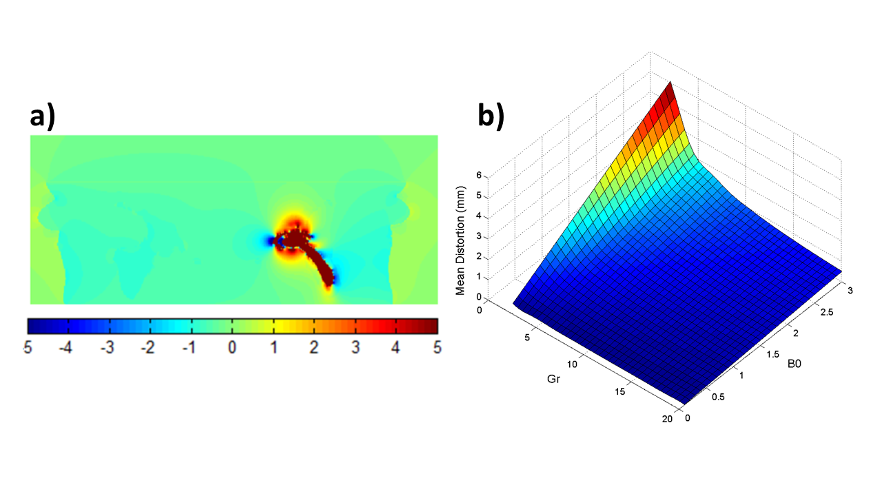
Figure 2. a) Shows the FDM magnetic
field simulation results for the coronal cut from Fig. 1a) – results were
converted from ppm to mm by assuming a 1.5T field and a 11 mT/m readout
gradient strength. Significant distortions surround the implant, but they rapidly
decrease away from femur structure. In contrast, the right femur shows
negligible spatial distortions. b) Mean distortions experiences by the
soft-tissue surrounding the implant as a function of B0 and readout gradient
strength.