4347
Distortion Correction for Isotropic High-Resolution Diffusion Imaging Using 3D Simultaneous Multi-Slab (SMSlab) Acquisition1Center for Biomedical Imaging Research, Department of Biomedical Engineering, School of Medicine, Tsinghua University, Beijing, China, 2Neusoft Medical Systems Co., Ltd., Shanghai, China, 3Department of Radiology, Stanford University, Stanford, CA, United States
Synopsis
In EPI-based diffusion imaging, the geometric distortions become more severe with increased image resolution. Various post-processing methods have been proposed to correct for distortions, such as the top-up method and the field-mapping method. Nonetheless, for 3D isotropic high-resolution diffusion imaging, distortion correction becomes more challenging due to decreased SNR. In this study, we applied a modified distortion correction method, which was previously proposed for 2D imaging, to isotropic high-resolution diffusion imaging using 3D simultaneous multi-slab (SMSlab) acquisition. The modified distortion correction method performed well in both phantom and in vivo experiments. It also outperformed the conventional top-up and field-mapping methods.
Introduction
In EPI acquisition, B0 inhomogeneity induced distortions are manifested as geometric deformation and intensity variation. The conventional field-mapping method 1 can correct the image deformation, but not address the intensity variation problem. The conventional top-up method 2-5 can correct for both geometric deformation and intensity variation. However, top-up may fail in regions with low image SNR, rapidly varied local B0 inhomogeneity or severely piled-up pixels. Moreover, its computational complexity is high due to the complex estimation and optimization of the displacement map. A modified distortion correction method 6 was proposed for 2D high-resolution diffusion imaging. It combines the advantages of both the conventional field-mapping and top-up methods while overcoming their deficiencies. In this study, we tested its feasibility in isotropic high-resolution diffusion imaging using 3D simultaneous multi-slab (SMSlab) 7,8 acquisition. Traditional field-mapping and top-up methods were also compared.Methods
Data acquisition and reconstruction:This study was approved by the local Institutional Review Board and written informed consents were obtained from the healthy volunteers. The phantom and in vivo diffusion data were acquired using SMSlab with in-plane 4-shot interleaved EPI, and a 32-channel head coil on a Philips 3.0T Ingenia CX MR scanner (Philips Healthcare, Best, The Netherlands). Two protocols were performed:
(1) 1.2 mm isotropic: 10 slices per slab with 25% kz oversampling, FOV = 220×220×134 mm3, 6 diffusion directions, b = 600 s/mm2, TE/TR = 67/1500 ms, acquisition time=7 min.
(2) 1 mm isotropic: 12 slices per slab with 20% kz oversampling, FOV = 220×220×140 mm3, 1 diffusion direction, b = 1000 s/mm2, TE/TR = 79/1500 ms, acquisition time = 2 min 24 s.
Other parameters: 7×2 (RSMS = 2) slabs in total, adjacent slabs were overlapped by 2 slices, partial Fourier = 0.7, 1 b0 image, NSA = 1. Two opposite in-plane phase encoding (PE) directions, Posterior-Anterior (PA) and Anterior-Posterior (AP), were scanned.
B0 field maps were acquired using a 6-echo 3D GRE sequence, TR/TE/ΔTE = 6/1/0.7 ms, resolution = 3.4×3.4×2.4 mm3. The field maps were interpolated to the size of isotropic high-resolution diffusion images. The T2-TSE and T2-FLAIR images were acquired as the distortion-free reference.
The SMSlab data were reconstructed in a 3D-kspace framework 8.
Distortion correction:
Three distortion correction methods were conducted, including the top-up method in FSL 9, the conventional field-mapping method and the modified distortion correction method.
In the modified distortion correction method, the conventional field-mapping method was firstly performed for deformation correction. An intensity correction process was carried out thereafter to obtain the final undistorted images, in a pixel-wise calculation using the deformation corrected images encoded by two opposite PE directions 6. For the intensity correction of each DWI image, an alternative is to use the Jacobin matrix derived from the PA-AP phase-encoded b0 image pair.
Results and Discussion
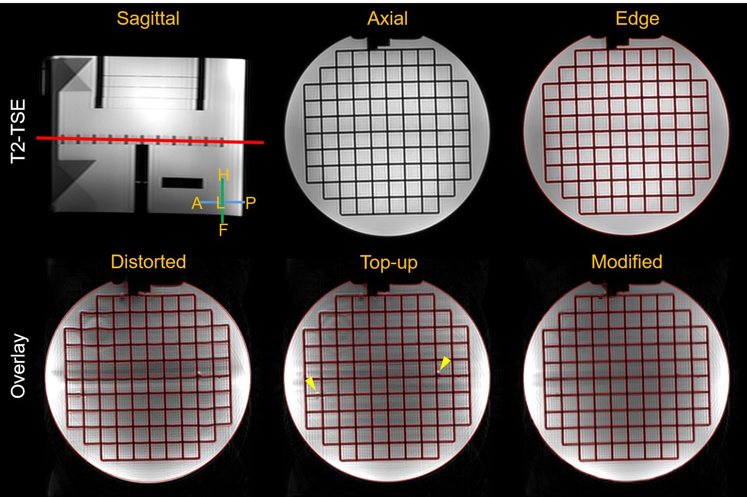
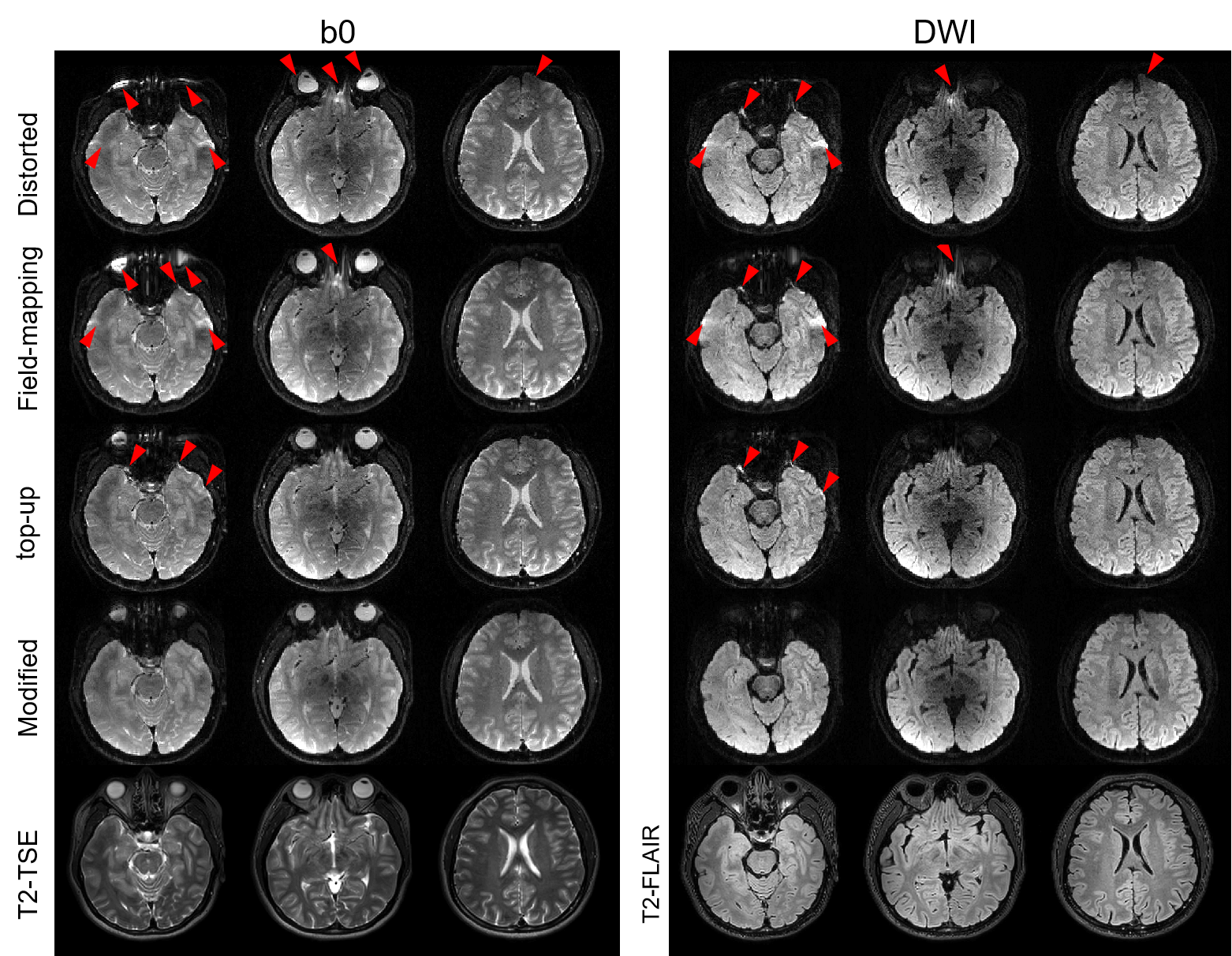
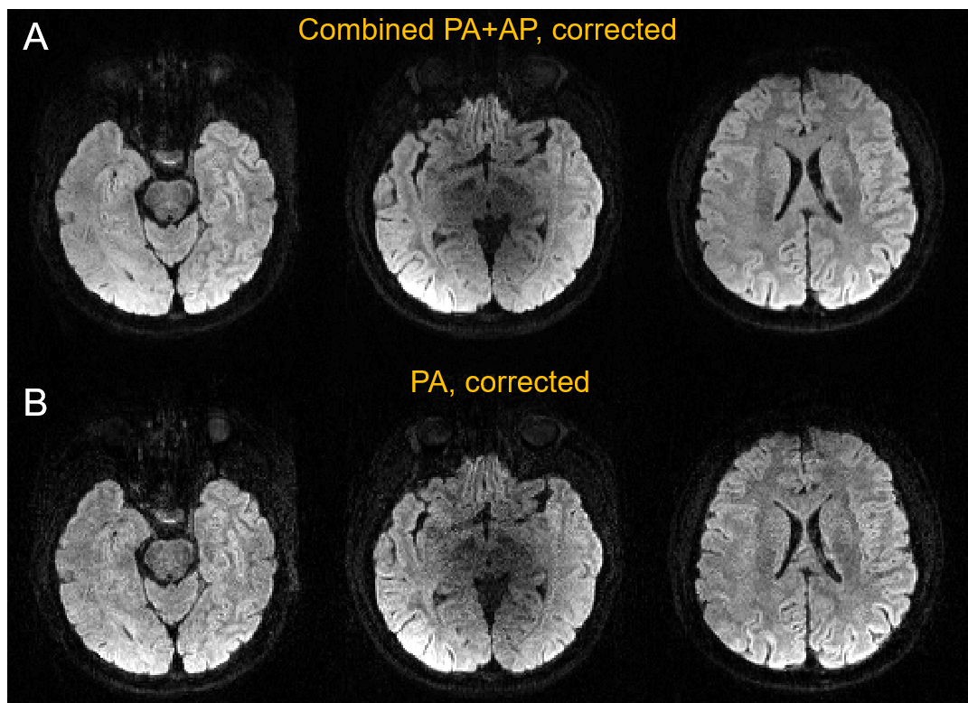
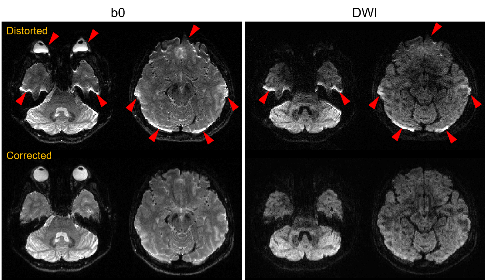
Figure 1 shows the 1.2 mm isotropic phantom results. Distortions are observed in the uncorrected images, shown as unmatched grid edges with the distortion-free T2-TSE image. In contrast, the grid edges in the images from top-up, modified distortion correction and T2-TSE are nearly identical. However, there are remaining distortions in the top-up corrected image (yellow arrows). The modified distortion correction method was able to remove these remaining distortions.Figure 2 shows the 1.2 mm isotropic in vivo results using different distortion correction methods. Using the top-up and conventional field-mapping methods, there are remaining distortions in areas with large susceptibility variations. While using the modified distortion correction method, these distortions are well corrected. In this method, the Jacobian matrix calculate from b0 images can also be used to correct DWI images (only in Figure 3B). Therefore, the acquisition time can be saved by acquiring a full set of PA phase-encoded DTI images and only one AP phase-encoded b0 image, though loosing the benefit of improving SNR through combining PA-AP images (Figure 3A).
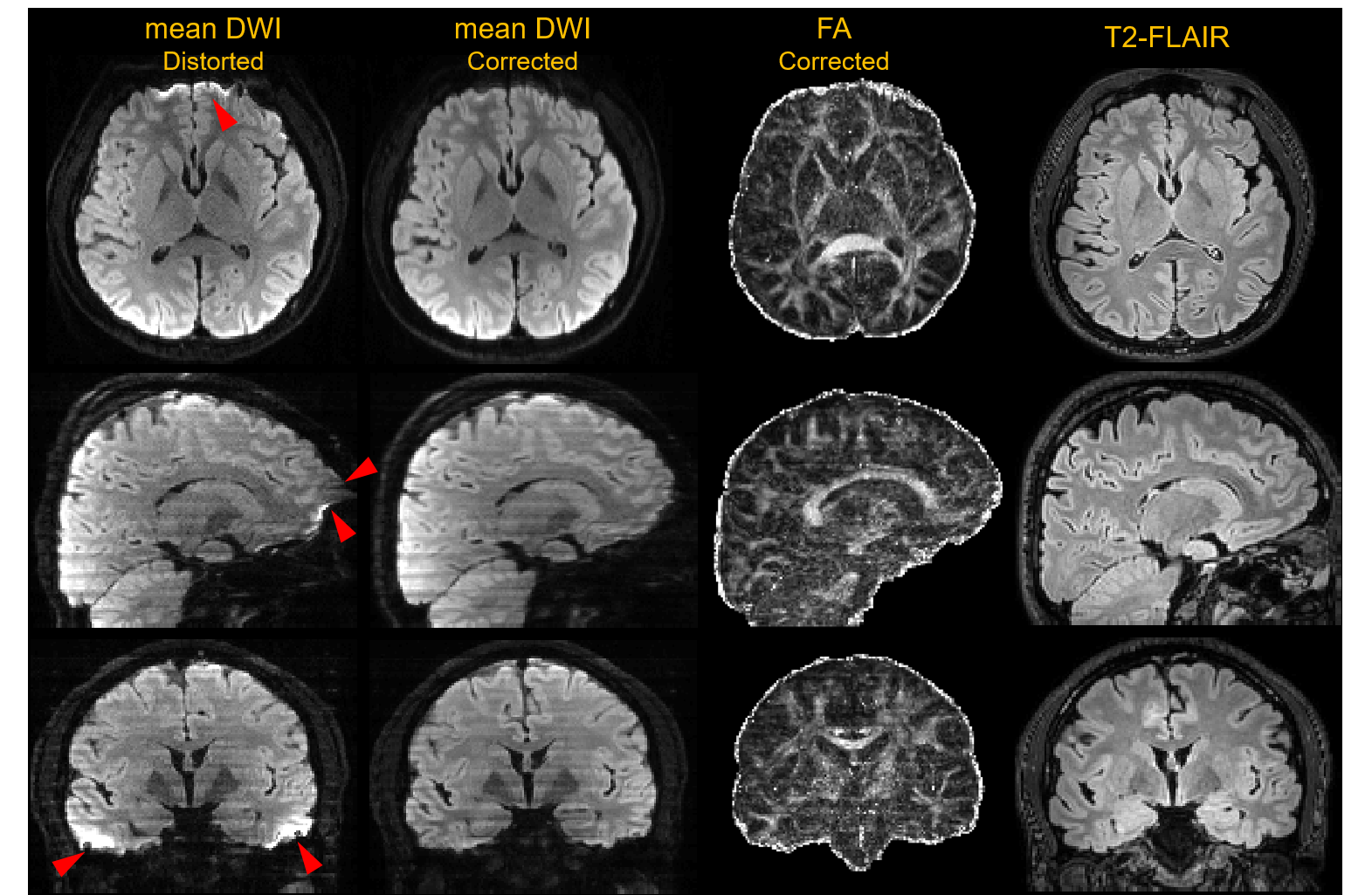
Figure 4 provides the distortion-corrected mean DWI and FA images in three orthogonal directions, using the modified distortion correction method.
Figure 5 demonstrates the distortion correction capacity of the modified distortion correction method on the 1 mm isotropic EPI images.
Conclusion
In distortion correction for isotropic high-resolution diffusion images acquired by SMSlab, the modified distortion correction method performed well in both phantom and in vivo experiments. In addition, it outperformed the conventional top-up and field-mapping methods.Acknowledgements
The Authors would like to thank Drs. Melvyn Ooi and Zechen Zhou from Philips Healthcare, and Ryan Robison from PCH for the help of reading raw data from the scanner.References
1. Jezzard P, Balaban RS. Correction for geometric distortion in echo planar images from B0 field variations. Magn Reson Med 1995;34(1):65-73.
2. Morgan PS, Bowtell RW, McIntyre DJO, Worthington BS. Correction of spatial distortion in EPI due to inhomogeneous static magnetic fields using the reversed gradient method. J Magn Reson Imaging 2004;19(4):499-507.
3. Holland D, Kuperman JM, Dale AM. Efficient correction of inhomogeneous static magnetic field-induced distortion in Echo Planar Imaging. Neuroimage 2010;50(1):175-183.
4. Andersson JLR, Skare S, Ashburner J. How to correct susceptibility distortions in spin-echo echo-planar images: application to diffusion tensor imaging. Neuroimage 2003;20(2):870-888.
5. Chang H, Fitzpatrick JM. A technique for accurate magnetic resonance imaging in the presence of field inhomogeneities. IEEE Trans Med Imaging 1992;11(3):319-329.
6. Xiong Y, Li G, Dai E, Wang Y, Zhang Z, Guo H. Distortion correction for high-resolution single-shot EPI DTI using a modified field-mapping method. NMR Biomed 2019;32(9):e4124.
7. Dai E, Wu Y, Wu W, et al. A 3D k-space Fourier encoding and reconstruction framework for simultaneous multi-slab acquisition. Magn Reson Med 2019;82(3):1012-1024.
8. Dai E, Wu Y, Guo H. High-Resolution Isotropic Diffusion MRI Using Simultaneous Multi-slab (SMSlab) Acquisition. In Proceedings of the 27th Annual Meeting of ISMRM. Montreal, Canada, 2019. p. 0774.
9. Smith SM, Jenkinson M, Woolrich MW, et al. Advances in functional and structural MR image analysis and implementation as FSL. Neuroimage 2004;23 Suppl 1:S208-S219.
Figures