4296
Optimizing Efficiency of Coupled Class-E RF Amplifiers for a Transmit Array System in 1.5 T1Electrical and Electronics Engineering, Bilkent University, Ankara, Turkey, 2-, Ankara, Turkey, 3ETH Zurich, Zurich, Sweden, 4Electrical Electronics Engineering, Bilkent University, Ankara, Turkey
Synopsis
In this work, performance of coupled Class-E amplifiers in a transmit array system is investigated. Conditions for these nonlinear amplifiers to work efficiently with desired output power are determined. Also a tuning procedure mitigating undesired effects of coupling on the performance of these nonlinear amplifiers is explained. Simulations are performed in ADS 2016 with 2 Class-E amplifiers and different coupling levels are tested. MRI experiment is performed in order to observe the effects of coupling on amplifier performance. With contour plots, how overall performance of the system is affected by phase and amplitude of an amplifier channel is investigated.
Introduction
The main purpose of this work is to replace the conventional RF amplifiers used in MRI systems with highly efficient on-coil array of modified Class-E amplifiers. Each amplifier in the transmit array may have various phase and amplitude. When tuned and highly efficient Class-E amplifiers are put together in a transmit array system, performance of the amplifiers degrades significantly due to the coupling between channels. In this work, conditions for achieving high efficiency with coupled Class-E amplifiers are stated; tuning procedure for the amplifier components is explained, the effects of phase and amplitude of the channel on the amplifier performance are observed. The operation of the amplifiers in a coupled system is simulated and MRI experiments are conducted on a 1.5T MR scanner. This work mainly focused on finding a mode of operation which satisfies high drain efficiency for the overall system and tuning nonlinear amplifiers in a transmit array system to optimize drain efficiency.Methods
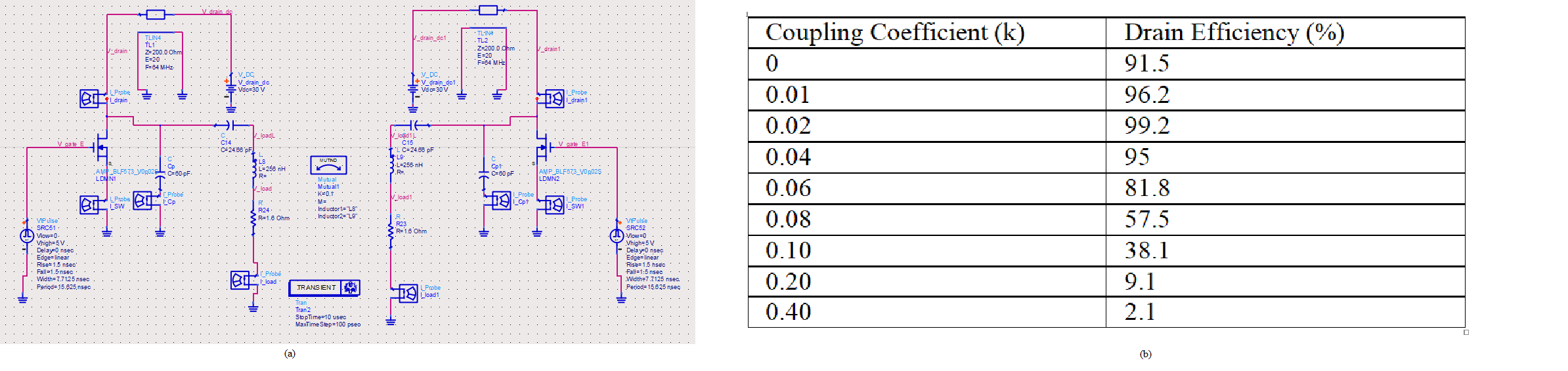
In the transmit array system, mutual coupling between each amplifier channel significantly affects the operation of Class-E amplifier. In order to observe this effect, two Class-E amplifiers which work simultaneously at 64 MHz are simulated in ADS 2016. Figure 1 shows the simulation parameters of the amplifiers with mutual coupling determined by coupling coefficient (k). Drain efficiency is monitored in the simulation for different coupling coefficients. Drain efficiency of the Class-E amplifier decreased significantly with high mutual coupling and the tuning is distorted.In order to improve the efficiency of amplifiers in a transmit array, N.O. Sokal’s explanation1 over tuning a single amplifier is utilized. Figure 2 shows the effect of load components on the switch voltage waveform. Positive coupling between the amplifiers cause an increase in the inductance of load network therefore the waveform will be shifted as Figure 2. In order to eliminate this negative effect on the amplifier efficiency, series load capacitor should be decreased. Likewise if the coupling between the amplifiers is negative, the system can be tuned again by increasing the load capacitor value.
Parameter sweep simulations are performed by varying the phase and the supply voltage of the Class-E amplifier in a coupled transmit system. Conditions enable the coupled amplifiers to deliver RF power with high efficiency are determined. Limits of the phase difference and the amplitude for this highly efficient operating mode are investigated with simulations.
Results
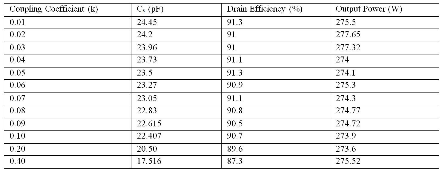
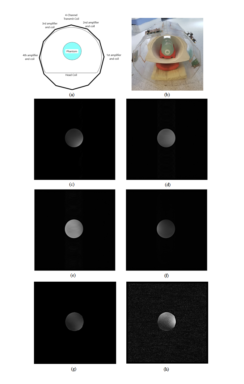
In order to demonstrate tuning procedure in the coupled system, simulations are performed in ADS 2016 with 2 Class-E amplifiers. Previously, each channel is tuned to deliver 275.6 W RF power at 64 MHz frequency with a drain efficiency of 91.5%. When two channels are coupled, tuning point shifts. This effect distorts the resonance frequency and reduces the efficiency of the amplifier. Then, tuning procedure is applied for positive coupling case. The series load capacitor value (Cs) is decreased to achieve similar output power with high drain efficiency. For each coupling level, optimum load capacitor value and corresponding drain efficiencies are listed in Figure 3.After tuning procedure, each amplifier can achieve almost the same performance in the transmit array like a single tuned amplifier. In the previous study2, the modified Class-E amplifiers for 2-channel transmit array system is proposed. To investigate the effect of coupling, MRI experiments with 4-channel transmit coil are conducted in 1.5 T scanner with the previous design of Class-E amplifier2. 63.795 MHz RF signal is given and 2ms sinc pulse signal is generated by the modified Class-E amplifiers.The MRI experiments are performed with 4-channel transmit coil and modified Class-E amplifiers. Figure 4.a shows how the transmit loops and Class-E amplifiers placed on the 4-channel coil.
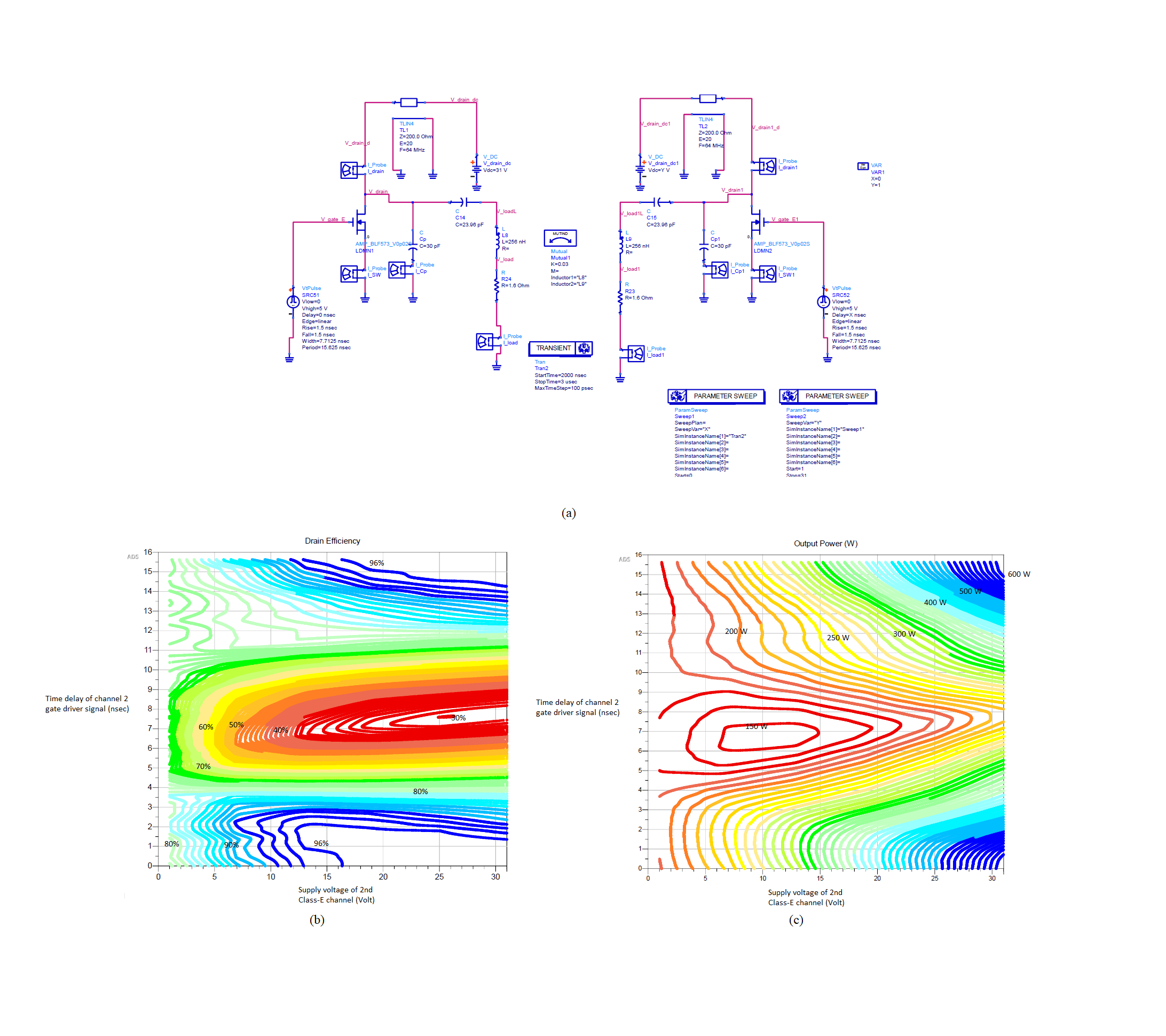
In order to determine optimum regions for overall efficiency and to observe the effect of load variation, parameter sweep is performed with coupled Class-E amplifiers. Initially, two amplifiers are tuned and adjusted to deliver 612 W output power with 96% drain efficiency. Then, phase and supply voltage of channel 2 are swept from 0 to 360 degree and from 1 V to 31 V respectively. By the simulation, optimum operating regions are detected; effects of phase and amplitude of second channel on the overall performance is investigated.
Discussion
Results showed that by applying proposed idea, highly efficient operating points can be found for coupled Class-E amplifiers, negative effects of coupling on load impedance can be minimized by tuning procedure and coupled amplifiers can deliver desired RF power with high efficiency in a transmit array. Also simulation results of coupled system are consistent with the proposed idea. Contour plots show which regions are favorable for achieving high efficiency in the coupled amplifier system.Conclusion
Class-E power amplifier can be used as on coil amplifier for parallel transmit array in MRI. In this work, the performance and operation of coupled Class-E power amplifiers are investigated. Conditions satisfying high drain efficiency for coupled amplifier system are determined, tuning procedure is implemented in order to expand highly efficient operating region of coupled Class-E amplifiers. It is shown that coupled Class-E amplifiers can be tuned, they can operate with high efficiency and high output power in a transmit array system despite phase limits.Acknowledgements
No acknowledgement found.References
1. Sokal NO. Class-E switching-mode high-efficiency tuned RF/microwave power amplifier: improved design equations, IEEE MTT-S International Microwave Symposium Digest, 2000.
2. Zahra F. MS Thesis: Highly Efficient 300W Modified Class-E RF Amplifiers for 64MHz Transmit Array System, Bilkent University, 2017.
Figures