4293
Design considerations for short-wave motion tracking1Institute for Biomedical Engineering, ETH Zurich and University of Zurich, Zurich, Switzerland
Synopsis
RF short-wave based motion tracking offers interesting prospects by allowing to localize markers without line of site, minimal interaction with the MRI scanner, very short latency and high precision. The design of the employed antenna arrays is however determinant for the performance of the entire system and subject to various requirements. The design criteria and parameters have hence been analyzed and used for optimization of the receiver array geometry. The resulting arrays have then been evaluated using signal simulations as well implemented and verified by bench measurements using a robotic positioning system as reference.
Introduction
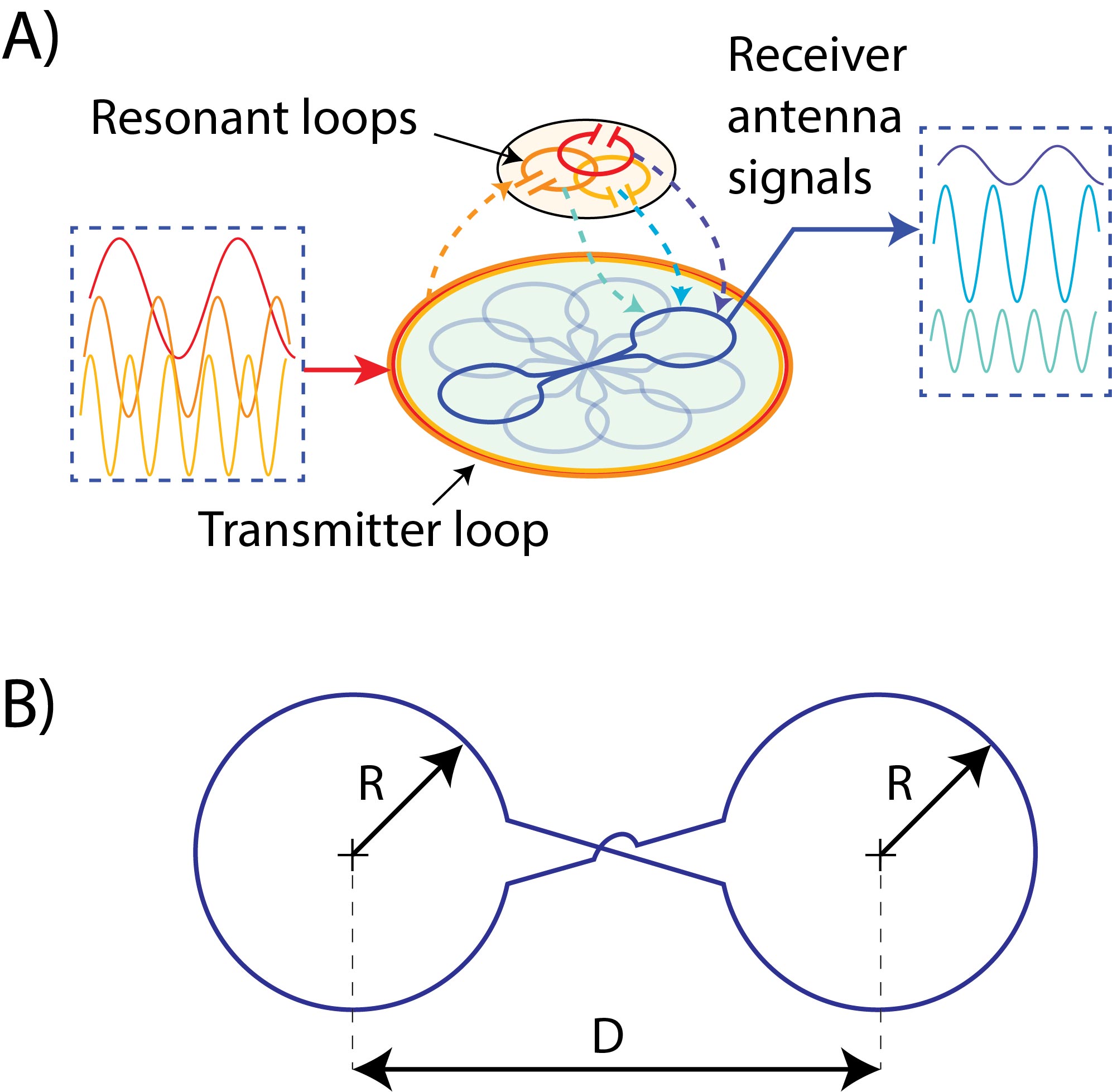
Motion tracker systems operating independently and decoupled from the MRI scanning process proved to be particularly versatile and optical detection [1, 2, 3] found the widest spread application. Recently a novel non-optical method [4] has been introduced using short-wave RF signals to track a wireless marker (Fig. 1) offering many advantages i.e. high precision and temporal resolution, low latency as well as requiring no line of sight at all even penetrating tissue.Low power RF transmitter and an array of receiver antennas is employed to locate a marker containing several small loops which are resonated at different frequencies of few MHz. The position of the reflector is then determined by an inversion of the calibrated position-to-signal relation.The precision of the obtained position and orientation data depends on the conditioning of the position encoding provided by the antenna arrangement. The tracking range is defined by the space within which the precision is sufficiently high. The design of the antenna is hence determinant for the performance of the system.Although many aspects above prompt analogies to the design of MRI receiver arrays, critical differences exist from the underlying coupling mechanism and encoding problem. Therefore, basic design considerations for short-wave motion trackers shall be described in the present work.Methods
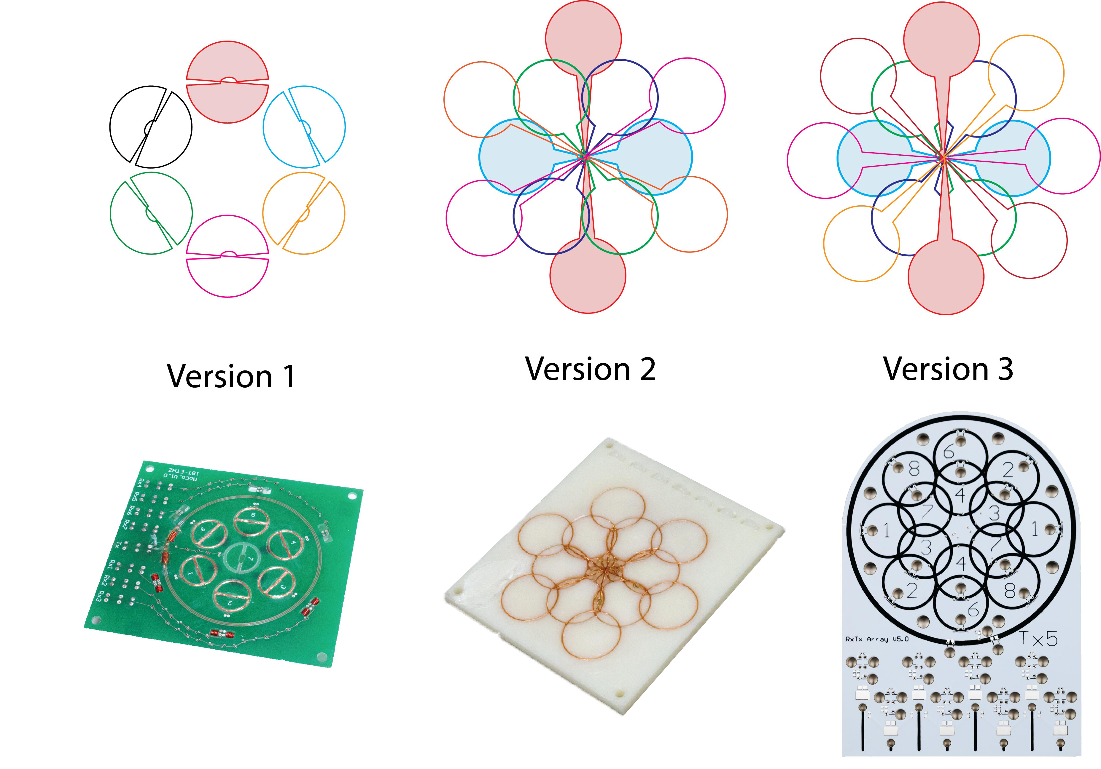
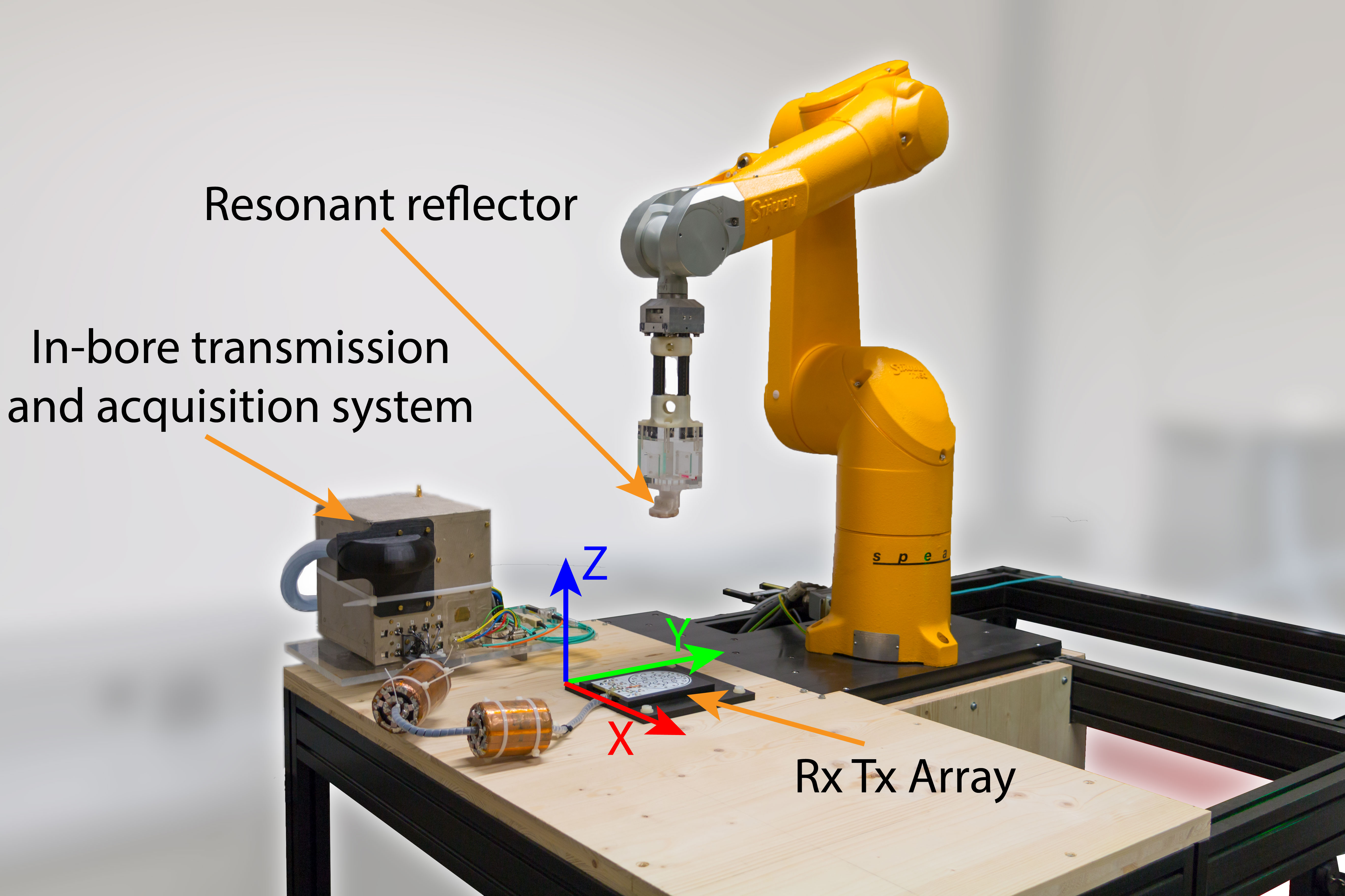
The basic arrangement of the short-wave tracker antenna array comprises a transmitter and and an array of receivers operating at 1 to 5 MHz. The receivers need to be highly decoupled from the transmitter to limit the dynamic range requirements since they operate simultaneously. Furthermore, the receivers need to exhibit limited coupling among each others and to the RF coils of the MRI system. These requirements can be fulfilled by configuring the receivers as gradiometers inside a transmitter loop.Each of these gradiometers has two geometrical degrees of freedom, the radius of the two loops (R) and their spacing (D) (Fig. 1). Furthermore, the effect of combining the encoding capabilities of the receivers in an array has been studied by comparing three different arrangements (Fig. 2):Version 1: Transmitter loop encompassing 6 receivers with equal radii and distances of 6.25mm.Version 2: 6 receivers (R=9.5mm) point-symmetrically arranged about the centre of the transmitter loop. An inner fan of receiver (D=31.5mm) and an outer fan (D=54.5).Version 3 has the same receiver architecture as version 2 (R of 9.5mm, D1 of 29.5mm, D2 of 51.5mm)but has four instead of three receivers in the outer fan. Furthermore, the array was fabricated as multilayer PCB and has RF traps in each of the loops tuned to decouple the tracker antenna from the RF coils used for MR imaging. The characteristics of the different versions are evaluated with a robotic test bench shown in Fig. 3. Furthermore, simulations based on biot-savart’s law were performed as shown in Fig. 4.Results
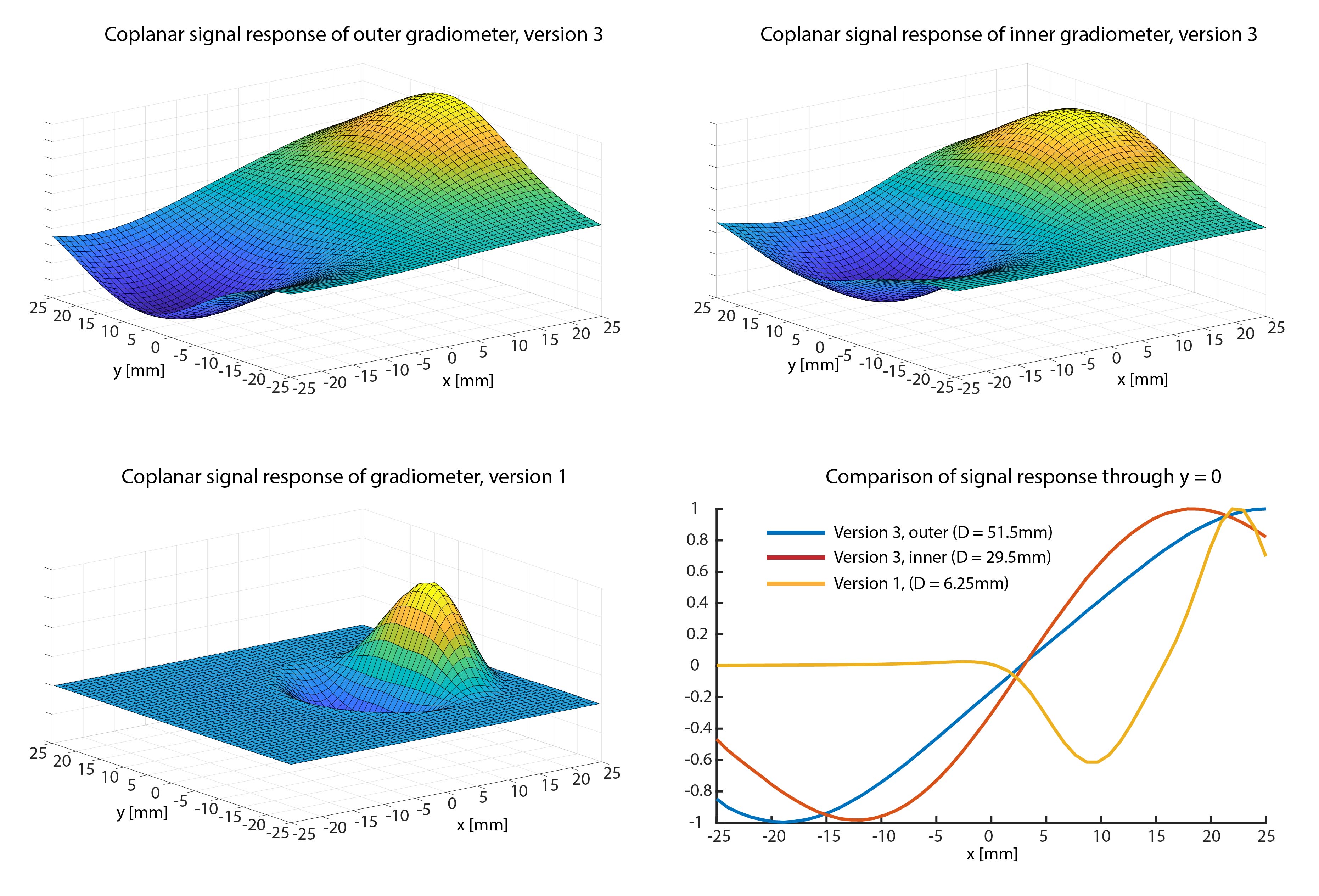
As the simulation in Fig. 4 shows a gradiometer is sensitive to all motional degrees of freedom of the reflector, except rotation around its rotation symmetric axis (being resolved by multiple resonators in the marker). However, the local gradient drops on the order of the size of the antenna. The signal response as a function of D is shown in Fig. 5. Its amplitude along the gradiometer forms almost a constant gradient over a distance of D optimally encoding the position. However, while the spatial extent of said gradient increases with D, the slope of the gradient decreases equally lowering the precision determination. The combination of two D values in version 2 and 3 results hence in an almost linear slope over the entire range as shown in Fig. 5.Discussion & Conclusion
The proposed design process allows targeting a tracker array to a particular range and precision requirement within the physical limits. The PCB based manufacturing process enables a reproducible, geometrically accurate and economical implementation. The resulting array (Version 3) renders a precision of (3µm,3µm,3µm),(12mdeg,11mdeg,10mdeg) at 100 Hz sampling rate, which is appropriate for tracking of head motion in an head MRI coil.The found differences to MRI receiver array are: An overall high detection sensitivity or uniformity is not required. E.g. a signal minimum can well encode a position while a spatially uniform coupling amplitude does not. The reflector does not couple to a circularly polarized magnetic field component but to a linearly polarized, correspondingly the respective reciprocity relations differ.Decoupling of transmitter and receiver antennas is required to be smaller than the coupling to the reflector not to challenge the dynamic range and stability of the measurement. Similarly decoupling to the RF coils employed for the detection of NMR signals has to be ideally provided permanently, which could however be ensured by use of traditional RF trapping circuits.The array elements are broad-band, non-resonantly matched which keeps the mutual inductive coupling comparably low. The frequencies of operation are low and penetration of the lossy tissue of subject does not significantly load the antennas nor the resonators in the marker. Hence, the position encoding model stay unaffected by the subject.Acknowledgements
No acknowledgement found.References
[1] Zaitsev, M., Akin, B., LeVan, P., & Knowles, B. R. (2017). Prospective motion correction in functional MRI. NeuroImage, 154, 33–42.
[2] Zaitsev, M., Dold, C., Sakas, G., Hennig, J., & Speck, O. (2006). Magnetic resonance imaging of freely moving objects: prospective real-time motion correction using an external optical motion tracking system. NeuroImage, 31(3), 1038–1050. https://doi.org/https://doi.org/10.1016/j.neuroimage.2006.01.039
[3] Slipsager, J. M., Ellegaard, A. H., Glimberg, S. L., Paulsen, R. R., Tisdall, M. D., Wighton, P., … Olesen, O. V. (2019). Markerless motion tracking and correction for PET, MRI, and simultaneous PET/MRI. PLOS ONE, 14(4),
[4] Schildknecht C et al, Wireless motion tracking with short-wave radiofrequency, Proc. Intl. Soc. Mag. Reson. Med. 27 (2019)
Figures