4289
Invisible receiver arrays? Proof of effective long distance RF arrays when tissue loss dominates1Imaging and Oncology, UMC Utrecht, Utrecht, Netherlands, 2Multiwave Innovation, Marseille, France, 3Multiwave Innovation, Geneva, Switzerland, 4Tesla Dynamic Coils, Zaltbommel, Netherlands
Synopsis
High-quality MRI uses arrays of local receiver coils positioned close to the region of interest to maximize acceleration performance and SNR in the images. This comes at the expense of patient comfort, particularly when considering surgical interventions under close to real-time MRI guidance. Here we demonstrate that when the tissue dominates the noise source over the electronic noise, the distance of the coil array to the tissue can be increased beyond the head to the bore liner of a head MR system without substantially decreasing the acceleration performance and intrinsic signal to noise compared to commercially available head coils.
Introduction
Optimization of MRI receiver coils is based on maximizing capturing the flux from the emitting spins while ensuring a low noise figure (e.g., high SNR) and providing high spatial fidelity (e.g., high SENSE acceleration). Kumar et al. 1 had shown that at high RF frequencies, the tissue rather than the RF coil itself dominates the noise even at relatively small loop sizes. Hendriks et al. 2 demonstrated that tissue loss dominance can be maintained to 2 cm2 closely positioned loops for a 256 channel head array. Here we move in the opposite direction by sticking to the available number of receivers of traditional MRI systems (e.g., 16 - 32 channels) thus, at an increased loop size to investigate if the array can be positioned at a considerable distance from the head while maintaining tissue load dominance for excellent MRI performance. This is to balance performance to patient comfort or investigate the feasibility of putting the receivers behind the covers of a dedicated head-MRI system for sterile surgery under MRI guidance. This study compared a home build array at 38 cm diameter (head-MRI system) to a tight-fitting 20 cm diameter commercially available array at 3T using loaded and unloaded Q-factor measurements to assess the noise figure, RF simulations concerning ultimate intrinsic SNR3 and preliminary phantom and in vivo measurements to assess acceleration performance.Methods
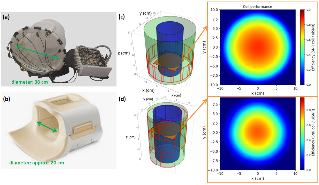
Inductively and preamp decoupled loops were positioned on a 38 cm diameter former, which determined the size of the elements (9.5 x 12.5 cm). Loaded and unloaded Q factor measurements were obtained from a single element positioned without a load and at 1 and 10 cm distance from the head of a volunteer by taking S12 between a pair of weakly coupled pick up probes with a network analyzer. A 16 channel version was constructed and interfaced using low noise preamplifiers and direct digitization (TeslaDC, Zaltbommel, the Netherlands) in figure 1 (a), similar to the commercial coil in figure 1 (b).RF simulations of the two coil setups were performed (Multiwave Innovation, Marseille, France) as described by Lattanzi et al. 3 and normalized to the ultimate intrinsic SNR achievable with unlimited channels or coil combinations. Here, perfect electric conductors were used, and RF coupling between elements neglected.
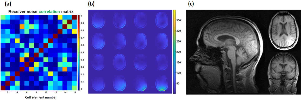
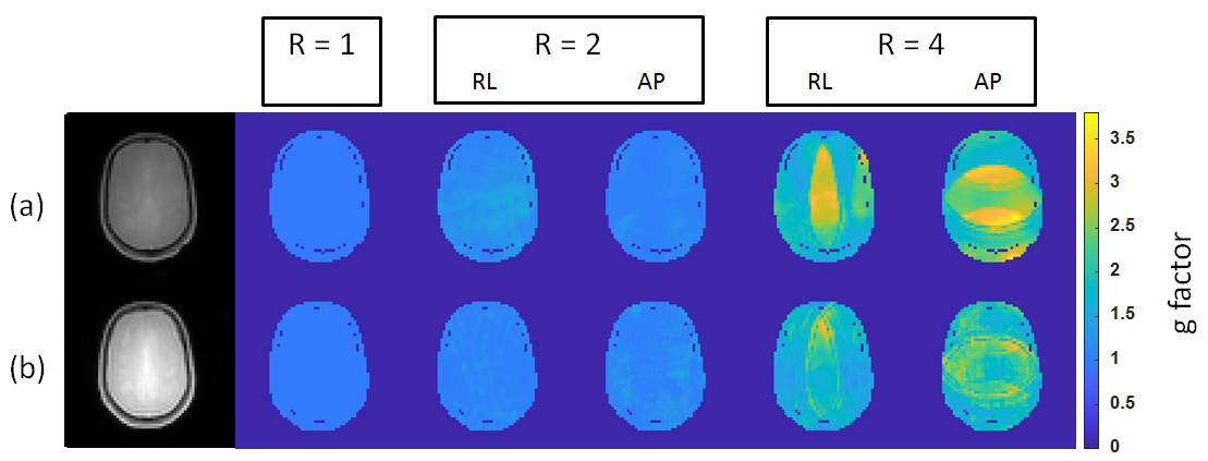
All MR measurements were acquired on a 3T MRI system (Ingenia, Philips, Best, the Netherlands). The g-factor of our single-row 16 channels array was compared to a commercial 15 channels head coil, composed of 7 loops on the head part and 8 loops on the base part coil (Philips, Best, the Netherlands). The anatomical images, SNR and g-factor maps were obtained with a 3D GRE sequence and the following parameters: FOV = 256 x 256 x 128 [mm3], voxel size = 4 mm isotropic resolution, TE/TR = 2/10 ms, FA = 3˚. The noise correlation was estimated from the noise data acquired without GR and RF excitation using the identical complex weighting between elements. Reduction factors (R) of 1 up to 4 were achieved using SENSE4 with 2 different phase encoding direction (i.e., AP and RL) to measure the g-factor.
Results and discussion
The loaded Q increased from 38 at 1 cm distance to 200 at 10 cm distance versus an unloaded Q of 460, showing that at this increased distance tissue loss remains dominant, resulting in a minor SNR loss of 20%. When neglecting the 20% SNR losses by the coil, simulations demonstrate similar SNR performance between the two coils in the center of the tissue in figure 1 (c,d) but reveal that SNR towards the periphery can theoretically be further improved when increasing the channel count. The high Q-factor of the loops challenge the RF coupling between elements, yet fair decoupling in the preliminary first version of the head array was obtained, providing good brain imaging performance in figure 2. No compromise in acceleration performance is observed up to R = 2 in either AP or LR direction when comparing the 38 cm coil to the 20 cm coil in figure 3. However, more noise amplification is observed at high acceleration (R = 4) of the 38 cm coil most probably caused by the suboptimal decoupling performance between the elements.Conclusion
Simulations and benchtop measurements revealed that SNR differences in the center of a wide aperture 38 cm diameter coil could be as little as 20% when compared to a commercially available tight-fitting head coil. The preliminary version of the 38 cm coil revealed good MRI performance and uncompromised noise amplification up to R = 2, albeit compromised at R = 4. These results encourage the design of dedicated sterile head MRI systems for surgery rooms.Acknowledgements
We like to thank Eurostars IMAGINE and Marie-Curie ITN INSPiREmed for financial support.References
1. Kumar A, Edelstein WA, Bottomley PA. Noise figure limits for circular loop MR coils. Magnetic resonance in medicine 2009;61(5):1201
2. Hendriks AD, Luijten PR, Klomp DWJ, Petridou N. Potential acceleration performance of a 256-channel whole-brain receive array at 7 T. Magn Reson Med. 2019 Mar;81(3):1659-1670
3. R. Lattanzi, G. C. Wiggins, B. Zhang, Q. Duan, R. Brown, and D. K. Sodickson, “Approaching ultimate intrinsic signal-to-noise ratio with loop and dipole antennas: Approaching Ultimate Intrinsic SNR With Loops and Dipoles,” Magn. Reson. Med., vol. 79, no. 3, pp. 1789–1803, Mar. 2018
4. Pruessmann KP, Weiger M, Scheidegger MB, Boesiger P. SENSE: sensitivity encoding for fast MRI. Magn Reson Med. 1999; 42: 952– 962
Figures