4286
Feasibility study of unshielded PET detectors with shielded RF coil for PET/MRI insert1Advance Nuclear Medicine Sciences, National Institute of Radiological Sciences (NIRS-QST), Chiba, Japan, 2Molecular Imaging and Theranostics, National Institute of Radiological Sciences (NIRS-QST), Chiba, Japan
Synopsis
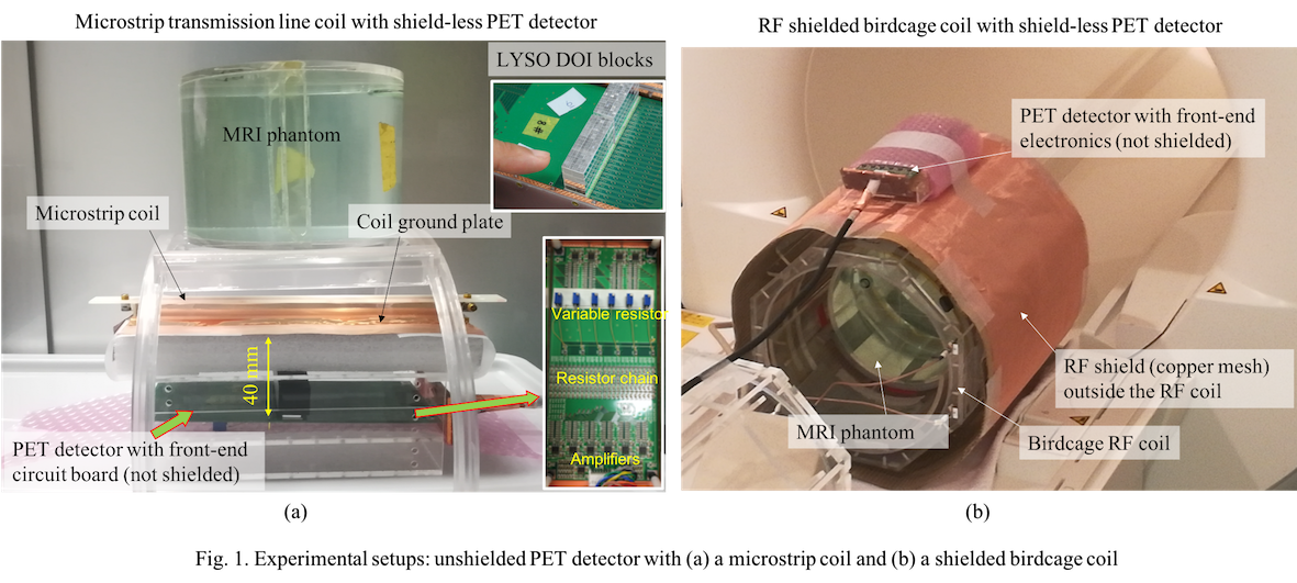
We used shielded RF coil in combination with unshielded PET detector. A microstrip coil and a head-size birdcage coil was used. For microstrip coil, the ground conductor acted as the shield, while for the birdcage coil a cylindrical RF shield was implemented. A PET detector with front-end electronics was implemented 40 mm far from the RF shields. Phantom studies revealed no RF pickup noise in any of these cases. A maximum 16% reduction in SNR was seen for the microstrip coil between PET detector powered OFF and ON conditions. However, the SNR reduction for the birdcage coil was negligible.
Introduction
One of the most important design challenges for the development of the PET insert for the MRI system is to avoid mutual electromagnetic (EM) interferences between the two systems. To avoid RF interferences, PET detectors are usually RF shielded [1-3] using conductive materials, like copper or carbon fibers. On the other hand, MRI system uses low frequency (e.g., 5 to 15 KHz) gradient fields. Although the gradient fields are almost transparent for the shielded PET insert, gradient eddy currents are generated in the shielding materials and the secondary eddy fields generates MR image artifacts [2-3]. Moreover, the shielding materials load the RF coil heavily and the RF coil with PET insert requires a larger RF power compared to the coil-only case [2]. Designing RF shielding materials for minimal gradient eddy current with minimal RF power has long been a design goal among the PET insert research groups. However, in almost all studies, completely enclosed Faraday shield cages were used as the basic shielding technique to shield the PET detectors and front-end electronics [1-3].On the other hand, RF coils, like the MRI built-in body RF coil [4] or the microstrip RF coils [5] are usually or can be optimally designed with RF shields. The body coil is accompanied by an external cylindrical RF shield to avoid external noise. For the microstrip coil, the ground conductor plate of the transmission line acts as the RF shield for regions outside the coil. In this study, we implementing unshielded PET detectors outside the shielding region of these RF shielded coils, where the RF field is negligible. We used a cylindrical head-size birdcage coil and a microstrip coil with an unshielded PET detector module and conducted phantom experiments with a 3T clinical MRI system for both PET OFF and ON conditions.
Materials and Methods
The microstrip coil was designed with a 12 mm wide and 250 mm long microstrip conductor and a 110 mm wide ground shield conductor of similar length. A PET detector with front-end electronics was positioned about 40 mm far from the coil ground plate, in which a homogeneous (NiCl2.6H2O and NaCl solution) cylindrical phantom (150 mm dia. and 100 mm long) was positioned 30 mm from the coil (Fig. 1(a)). 35 mm thick copper foil was used to construct this coil. On the other hand, the 8-element birdcage coil of diameter 270 mm and length 280 mm was shielded by a 360 mm diameter and 360 mm long cylindrical shield (Fig. 1(b)) made of copper mesh (mesh 200/inch, thickness 50 mm). For the PET detector, we reused a detector of a previously developed PET insert [2-3]. The scintillation crystal was LYSO type with single crystal dimensions of 2.0mmX2.0mmX4.0mm, array size of 16X16X4 and axial field-of-view of 32 mm. The detector was a SiPM (Hamamatsu Photonics KK, S12641PA-050) with 4.1mm pitch, which have 33 mm2 sensitive area. A homogeneous cylindrical phantom of dia. 200 mm and length 100 mm was used inside the coil. Both coils were used with a 3T clinical MRI system (Siemens MAGNETOM Verio). Gradient-echo (GE) and spin-echo (SE) images were taken for the following parameters: TR = 600 ms, TE = 4 ms (GE) and 12 ms (SE), flip-angle = 60 deg (GE) and 90 deg (SE), slice thickness = 10 mm, image matrix = 256 X 256, and FOV = 220 mm2 for the microstrip coil and, 300 mm2 transverse, and 250 mm2 coronal planes for birdcage coil. To calculate SNR [6], noise was calculated from the mean of four ROIs in the background and signal was calculated as the mean of approximately 70% central region of each image.Results and Discussion
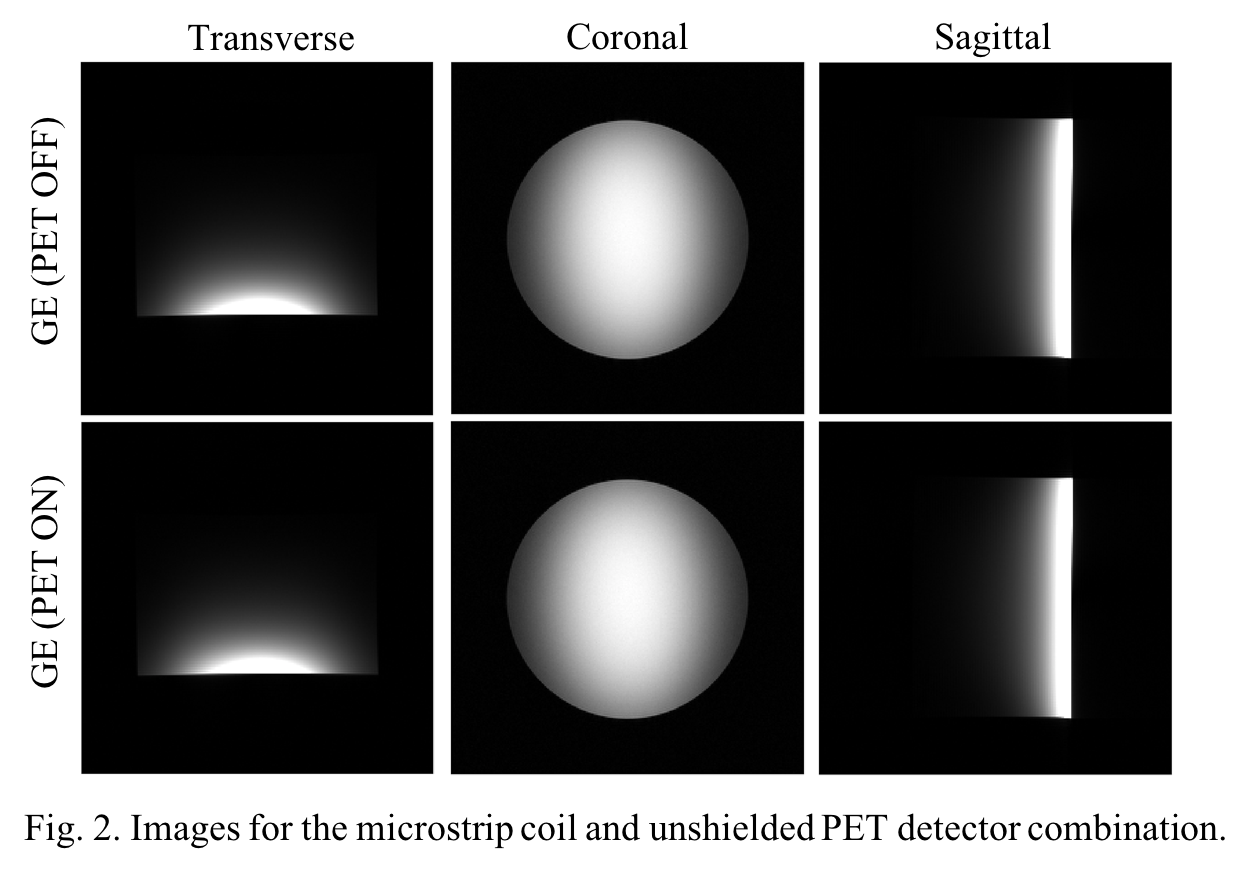
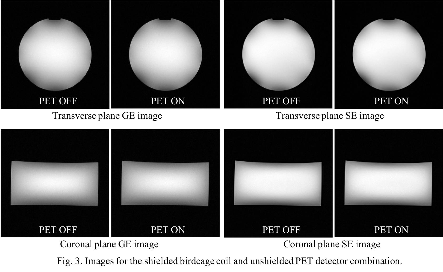
The GE images for the microstrip coil are given in Fig. 2. In multiple studies, we did not find any RF pick-up noise in the images. However, a slight increase in noise was found for the PET ON condition compared to the PET OFF condition. As a result, a maximum reduction of 16% in SNR values (Table 1) was seen for this case. In the case of multiple parallel microstrip coils, shielding would be better than a single coil. Fig. 3 illustrates images for the shielded birdcage coil with unshielded PET detector. We did not see any pick-up RF noise for this case also. Changes of SNR values between PET OFF and ON conditions were negligible for the case of birdcage coil. Since the birdcage coil was completely RF shielded, noise contamination was negligible in this case. From the count rate observation for different imaging sequences, we did not see any significant variation compared to the PET OFF condition.Conclusion
For the MR images, we did not see any significant effect of noise from the shield-less PET detector module. Further detail study would guide for the development of a minimal or a shield-less PET insert, in which the RF coil is tuned and matched with an RF shield.Acknowledgements
No acknowledgement found.References
[1] F. Nishikido et al. (2017). Development of a full-ring “add-on PET” prototype: A head coil with DOI-PET detectors for integrated PET/MRI, Nucl Instr Meth Phy Res A 863:55–61.
[2] M. S. H. Akram et al. (2017). MRI compatibility study of an integrated PET/RF-coil prototype system at 3 T. J. Mag. Reson. 283:62-70.
[3] P. Olcott et al. (2015). Prototype positron emission tomography insert with electro-optical signal transmission for simultaneous operation with MRI. Phys Med Biol. 60:3459–478.
[4] M. Collins, et al. (1997). A Method for Accurate Calculation of B1 Fields in Three Dimensions. Effects of Shield Geometry on Field Strength and Homogeneity in the Birdcage Coil. J. Mag. Reson. 125:233-241.
[5] G. Adriany et al. (2008). A geometrically adjustable 16-channel transmit/receive transmission line array for improved RF efficiency and parallel imaging performance at 7 Tesla. Magn Reson Med. 59:590–597.
[6] E. F. Jackson et al. (2010). Acceptance testing and quality assurance procedures for magnetic resonance imaging facilities. AAPM report no. 100, American Assoc Phys Med.
Figures