4283
Body imaging at 7T: Comparison of the transmit/receive performance of microstrip antennas and fractionated dipoles1Medical Physics in Radiology, German Cancer Research Center (DKFZ), Heidelberg, Germany, 2Electromagnetic Theory and Applied Mathematics, Faculty of Electrical Engineering and Information Technology, FH Aachen – University of Applied Sciences, Aachen, Germany, 3Erwin L. Hahn Institute for MRI, University Duisburg-Essen, Essen, Germany, 4Faculty of Physics and Astronomy and Faculty of Medicine, University of Heidelberg, Heidelberg, Germany
Synopsis
The transmit and receive performance of 8-channel array configurations of microstrip antennas with meander structures and fractionated dipoles was evaluated at 7T using numerical simulations. Simulations with a homogenous phantom and an anatomical body model use similar parameters to facilitate direct comparison. The microstrip antenna array configuration provides higher SNR than the fractionated dipole array configurations and shows superior RF shimming performance for large-FOV transverse and coronal slices, whereas single-element simulations estimate similar SAR efficiencies. The RF shimming performance of the array configurations does not differ significantly for smaller ROIs as evaluated for prostate imaging.
Introduction
RF transmit antennas for body imaging at UHF MRI remain an open research topic. Different antenna geometries have been proposed for body imaging at 7T: the fractionated dipole1 as well as the microstrip antenna with meander structures2 are antennas with a similar curl-free surface current pattern and have frequently been implemented. These antenna concepts show favorable results as shown in several analytical, simulation, and experimental studies1,3,4,5. However, a direct comparison of the two antenna types based on the published data is not possible, since every study uses different simulation and measurement parameters. To compare the individual antenna performance, a direct comparison was carried out using numerical simulations.Methods
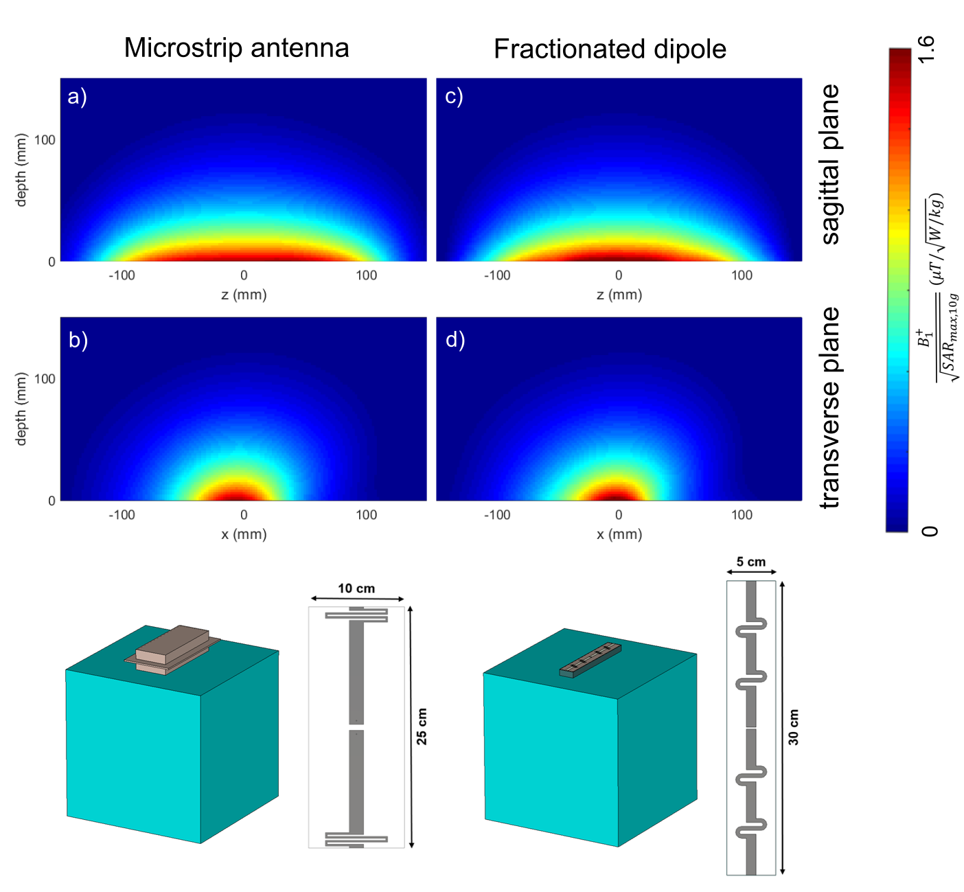
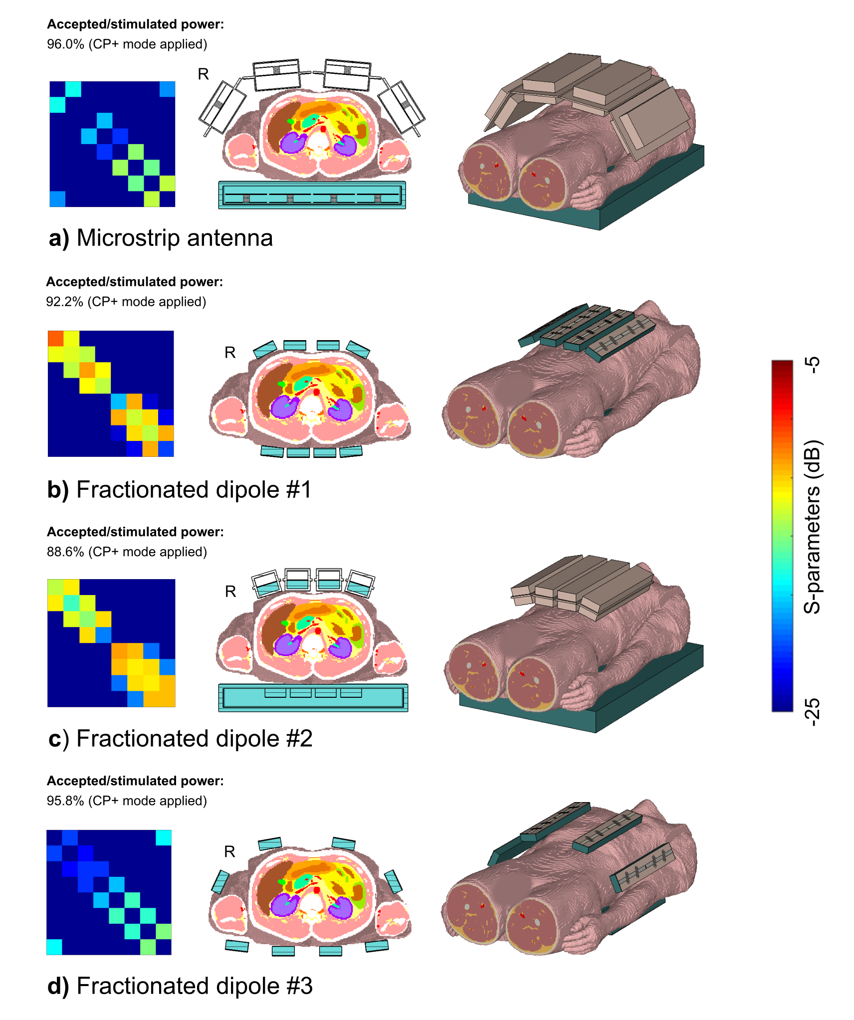
Fractionated dipoles and microstrip antennas with meander structures at the end of the stripline were simulated as single transmit elements as well as in an 8-channel local body array configuration.First, the SAR efficiency of the single elements was evaluated with a homogeneous, tissue-simulating phantom (0.5x0.5x0.5 m³, εr' = 44.2, σ = 0.57 S/m), Figure 1. Afterwards, simulations with a heterogeneous body model (male, 174 cm, 72.4 kg)6, head-first supine, with the liver-kidney region in the coil center were performed to evaluate the transmit and receive performance of the array configurations, Figure 2. The reference array configurations (microstrip antenna, fractionated dipole #1) were constructed similar to the respective publications1,7. Furthermore, the fractionated dipole was simulated with a supplemental element housing (#2) as used for the microstrip antenna for realistic simulations of in-vivo examinations. An additional array configuration of the fractionated dipole (#3) increased the circumferential spacing of the elements as applied for the microstrip antenna to improve comparison of entire transverse slices as the ROI. RF simulations were performed in CST Studio Suite (CST AG, Darmstadt, Germany).
B1+ and B1- maps for the individual channels as well as scattering (S-) parameters were extracted. SAR matrices were computed and compressed based on the VOP algorithm8.
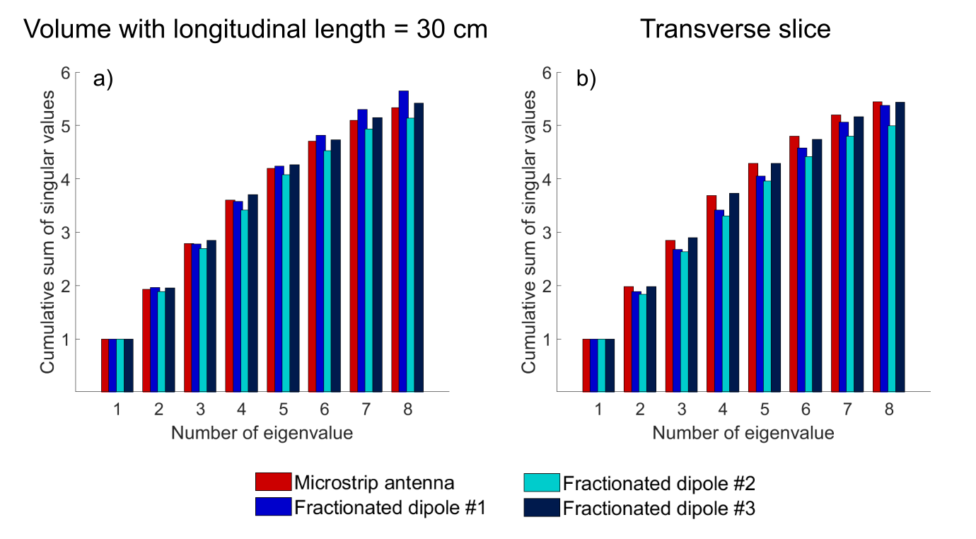
The normalized cumulative sum of the singular values of the complex B1+ maps were evaluated in a ROI with length of 30 cm along the longitudinal axis and within a complete transverse slice excluding the arms to estimate the available DOF for pTx methods.
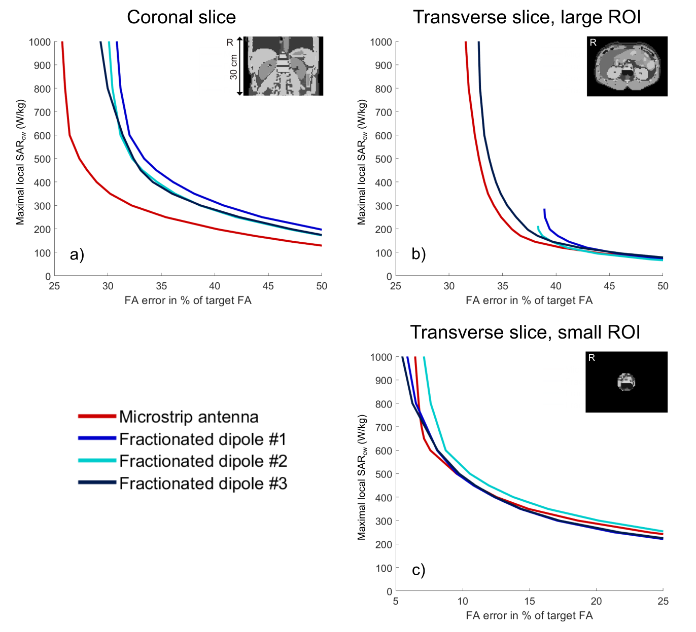
Additionally, the transmit performance was assessed using RF shimming for a target magnetization of 6.5 μT with peak power per channel of 1 kW and varying local SAR constraints9. A central transverse and a coronal slice with length of 30 cm were chosen as ROI as well as a smaller region defined as a circle with radius of 3.9 cm positioned centrally in the transverse slice.
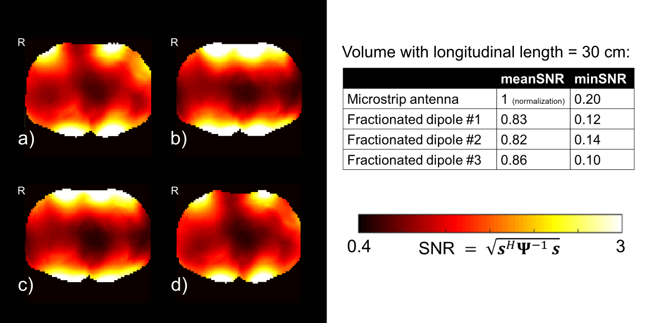
SNR maps corresponding to the receive performance were calculated by considering the receive sensitivities sj = B1,j-(x,y) of the coil elements as well as the noise correlation matrix ψ.
Results & Discussion
Figure 1 shows the simulated SAR efficiency for the two antenna concepts in a phantom. For the selected slices, the magnitude of the SAR efficiency is similar.For comparison of the array configurations, an element housing for the fractionated dipole was designed and the circumferential spacing was varied, Figure 2. For the fractionated dipole array #3, mutual coupling is as low as for the microstrip antenna configuration with the same circumferential spacing.
The cumulative sums of the singular values of the complex B1+ fields are shown in Figure 3. The fields are significantly correlated, since the cumulative sums are considerably smaller than the number of elements. The cumulative sums do not show a plateau for either of the ROIs or for any configuration. Differences between the configurations are generally small, but the fractionated dipole #1 achieves the highest cumulative sum in the volume with 30 cm length, whereas the microstrip antenna and the fractionated dipole #3 provide the highest sum in a ROI reduced to a single transverse slice.
RF shimming results are presented as L-curves in Figure 4. A duty cycle was not taken into account; however, the maximum allowed duty cycle can be calculated based on the respective local SAR limits. The microstrip antenna array shows the best performance in the transverse and coronal slice (FA error at SARcw of 800 W/kg: 32% transverse, 26% coronal). In the small transverse ROI, differences between the configurations are small; the fractionated dipole #1 and #3 achieve the lowest FA errors (6% FA error at SARcw of 800 W/kg), but this higher performance can only be achieved in few applications, since the applied duty cycle must be low.
Figure 5 shows SNR maps in the central transverse slice and presents the mean and minimum SNR in the larger ROI. The microstrip antenna configuration shows 16% higher mean SNR and an increase of the minimum SNR by a factor of two in comparison to the fractionated dipole #3.
Conclusion
For ROIs defined as an entire slice, array configurations with increased circumferential spacing of the elements achieve a better Tx/Rx performance. Furthermore, the microstrip antenna 8-channel array configuration shows superior RF shimming performance and higher SNR in comparison to the fractionated dipole. The evaluation of the RF shimming performance within a smaller ROI as used for prostate imaging shows only small differences between the antenna concepts.Acknowledgements
No acknowledgement found.References
1Raaijmakers et al. The fractionated dipole antenna: A new antenna for body imaging at 7 Tesla. Magn Reson Med. 2016; 75(3):1366-74.
2Orzada S, Bahr A and Bolz T. A novel 7 T microstrip element using meanders to enhance decoupling. In: Proceedings of the 16th Annual Meeting of ISMRM, 2008, #2979.
3Lattanzi R and Sodickson DK. Ideal current patterns yielding optimal signal-to-noise ratio and specific absorption rate in magnetic resonance imaging: computational methods and physical insights. Magn Reson Med. 2012; 68(1):286-304.
4Rietsch et al. Parallel transmit capability of various RF transmit elements and arrays at 7T MRI. Magn Reson Med. 2018; 79(2):1116-1126.
5Raaijmakers AJ, Luijten PR and van den Berg CA. Dipole antennas for ultrahigh-field body imaging: a comparison with loop coils. NMR Biomed. 2016; 29(9):1122-30.
6Christ et al. The Virtual Family--development of surface-based anatomical models of two adults and two children for dosimetric simulations. Phys Med Biol. 2010; 55(2):N23-38.
7Orzada et al. A flexible 8-channel transmit/receive body coil for 7 T human imaging. In: Proceedings of the 17th Annual Meeting of ISMRM, 2009, #2999.
8Eichfelder G and Gebhardt M. Local specific absorption rate control for parallel transmission by virtual observation points. Magn Reson Med. 2011; 66:1468–1476.
9Guérin et al. Design of parallel transmission pulses for simultaneous multislice with explicit control for peak power and local specific absorption rate. Magn Reson Med. 2015; 73(5):1946-1953.
10Fiedler TM, Ladd ME and Bitz AK. SAR Simulations & Safety. Neuroimage. 2018; 168:33-58.
Figures