4280
Miniaturized Quadrature Hybrid Coupler Using Coaxial Cable with Inductive Loading for 1.5T MRI System1Technology Innovation Department, Society for Applied Microwave Electronics Engineering and Research, Mumbai, India
Synopsis
To improve the homogeneity of magnetic field and SNR of the Image by a factor of , quadrature feeding is required. For Quadrature Feeding, Hybrid coupler is an essential microwave circuit, but at RF range the size of hybrid coupler is large. To make it miniaturized and to overcome the problem of power handling capacity (compared to lumped element) we have proposed coaxial cable with inductive loading. This technique minimizes the size of hybrid by 75% and has a coupling of 3dB and phase difference of 900 at 63.87MHz.
Synopsis
To improve the homogeneity of magnetic field and SNR of the Image by a factor of √2, quadrature feeding is required. For Quadrature Feeding, Hybrid coupler is an essential microwave circuit, but at RF range the size of hybrid coupler is large. To make it miniaturized and to overcome the problem of power handling capacity (compared to lumped element) we have proposed coaxial cable with inductive loading. This technique minimizes the size of hybrid by 75% and has a coupling of 3dB and phase difference of 900 at 63.87MHz.Introduction
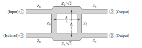
A hybrid is a Special class of four port Directional Coupler with distinguished Property of dividing equal half power with 900 phase shifts at its two-output port. Figure 1 shows model of classical hybrid coupler. Many feeding networks in MR system such as Birdcage coil1, requires In-phase (00) and Quadrature (900) phase with equal power division with good isolation between them. At RF frequency, size of coupler is in few meters. To minimize its size and also to overcome the problem of high-power handling, we have presented novel design using coaxial cable with inductive loading. Presented Hybrid Coupler is designed based on mathematical and simulated data. The Prototype has an operating frequency of 63.87MHz with return loss, and isolation of 27dB whereas phase difference of 900 between output ports. Overall Size Reduction takes place by 75% compared to conventional hybrid coupler.Method
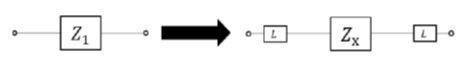
There are mainly two types of loading which are used to minimize the size of circuit in RF and Microwave Regime. These are capacitive and inductive loading. Capacitive loading can be used to minimize the size of Wilkinson Power diver2. Inductive loading can also be used to minimize the size of Power Divider/Combiner3. Main difference between them is that in capacitive loading characteristic impedance increases while in inductive loading it decreases. Consider transmission line of any characteristic impedance (any arbitrary length) and load it with inductor as shown in figure 2. Procedure to know length and impedance of miniaturized hybrid coupler is mentioned as below:ABCD matrix of Transmission Line and Isolated Inductor are given as
$$M_{TX}= \begin{bmatrix}Cos(βι) &jZSin(βι) \\jYSin(βι) & Cos(βι) \end{bmatrix} , M_{L} = \begin{bmatrix}1 & jwL \\0 & 1\end{bmatrix}$$
Final ABCD matrix of inductive loaded section is given as
$$M_{final}= M_{L} \times M_{TX} \times M_{L} $$
Solving for above multiplication and equating with corresponding elements in ABCD matrix of Initial Transmission line. We get,
for vertical arm,
$$L= \frac{Z_0 Cos(βι)}{ω}\cdot\cdot\cdot\cdot\cdot\cdot\cdot\cdot\cdot\cdot(1)$$ and $$Z_x=Z_0 Sin(βι)\cdot\cdot\cdot\cdot\cdot\cdot\cdot\cdot\cdot\cdot(2)$$
where,
L = Inductor Value for miniaturized section.
Z0 = Characteristic Impedance of Original Section.
Zx = Characteristic Impedance of miniaturized section.
βι = Electric length of new section.
For horizontal arm,
$$L= \frac{Z_0 Cos(βι)}{√2ω} \cdot\cdot\cdot\cdot\cdot\cdot\cdot\cdot\cdot\cdot(3)$$ and $$Z_x=\frac{Z_0 Sin(βι)}{√2} \cdot\cdot\cdot\cdot\cdot\cdot\cdot\cdot\cdot\cdot(4)$$
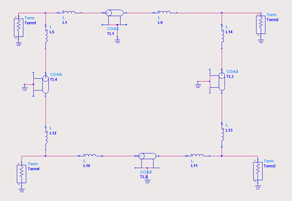
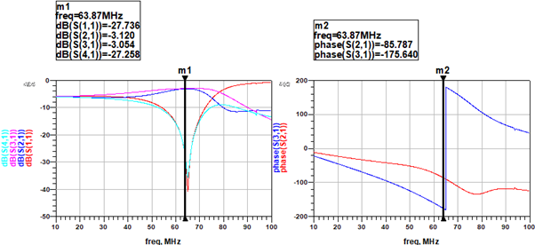
Here we have to fix the value of either Zx or L as per user choice and availability. Here, we have taken Zx as 18Ω (Coax cable TC18, company Richardson RFPD) and calculated value of inductor and length of cable by using equations (1),(2),(3),(4) for frequency 63.87MHz. On performing mathematical calculation we get, Inductor value (L) of vertical arm as 115.25nH (length=20cm) & horizontal arm as 74.45nH (length=29cm). With above values proposed design (figure 3) is simulated in software ADS v.16 and its results are shown in figure 4.
Results
Return Loss (S11) – 27.736dB, Isolation (S41) – 27.25dB, Coupling between output port – 3dB, Bandwidth- 18MHz, Phase difference – 900, Size of Hybrid Coupler without Inductive Loading – 1.17 meter, Size of Hybrid Coupler with Inductive Loading – 0.29 meter, and Size reduction takes place by - 75 %.Discussion & Conclusion
From the mathematical and simulation results, we designed quadrature hybrid coupler which minimizes the size by 75%. Use of Coax cable for hybrid coupler also overcomes the problem of power handling capacity over lumped and microstrip element coupler. It also gives low insertion loss as compared with lumped element. This novel design is compact, light-weight, and consumes minimum area in the system. This design may potentially be used for 1.5T MR System for feeding network like Body birdcage, Head birdcage coil etc which require in-phase and quadrature output with equal power division.Acknowledgements
No acknowledgement found.References
1. Niraj S.Y., Inderkumar K., Tapas K.B., Rajesh H., “RF Transmit/Receive Quadrature Fed Body Birdcage coil for 1.5T MR System”, IEEE International Conference on Electronics, Material Engineering and Nanotechnology, 2018.
2. Maximilian C.S., George E.P., and Thomas M.W., “Miniaturized Wilkinson Power Dividers Utilizing Capacitive Loading”, IEEE Microwave and Wireless Components Letters Vol.12, Issue 1, Jan. 2002.
3. Vishal D.B., Ruchira V., Tapas K.B., Rajesh H., “Power divider/Combiners for 1.5T MRI Solid State Amplifier”, IEEE International Conference on Electronics, Material Engineering and Nanotechnology, 2018. 4. David M. Pozar, “Microwave Engineering” 4th edition, Wiley Publication, 2012 Page no. 343-346.
Figures