4279
Analysis of the effects of Absorptive Switch v/s Reflective Switch on the performance of Hybrid Coupler designed for Birdcage coil at 1.5T MR System1TID, Society For Applied Microwave Electronics Engineering & Research, Mumbai, India
Synopsis
Volume coils such as the Birdcage Coil possess homogeneous magnetic fields due to circularly polarized fields assisted by the Hybrid Coupler. To perform the complete operation of the birdcage coil for imaging, the Transmit power must be well isolated from the receive front end which is done by introducing RF switches in the receive path. However, Reflective switches cause impedance mismatch at the ports of the coupler. This work demonstrates an absorptive switch due to which the impedance mismatch problem is solved. Also, comparative analysis were done for both the type of RF switches.
Synopsis
Birdcage coil when used as a transceiver coil for generating circularly-polarized fields must operate in Quadrature mode. This is done with the help of a Hybrid Coupler. Further to isolate the RF leakage signal in the receive path switches are introduced. However, introducing an RF reflective switch in the receive path changes the impedance at the receive port of the Coupler which causes impedance mismatch at the coil terminals. We have inserted an absorptive switch in the receive path of the coupler with an insertion of 0.45dB and isolation of 22.48dB which ensures no impedance mismatch.Introduction
Birdcage coil is well known for generating homogeneous magnetic field inside it through circularly polarized fields in quadrature mode1. These fields are generated with the help of a Hybrid Coupler. The power exchange between the coil and the hybrid coupler must be efficient and it is only possible if all the ports of the hybrid are 50Ω matched. Also, to protect the Receiver front-end chain, RF switches are used. Reflective switch when used changes the impedance at the receive port and hence there is mismatch in impedance. Hence, to maintain the impedance matching absorptive switches must be used2. Operation of the PIN diode in the switches as a switching element if examined properly generates number of design techniques3. The chosen design is for an absorptive switch which is interfaced with the hybrid coupler and its results are compared with the results obtained from that of an already designed reflective switch.Methods
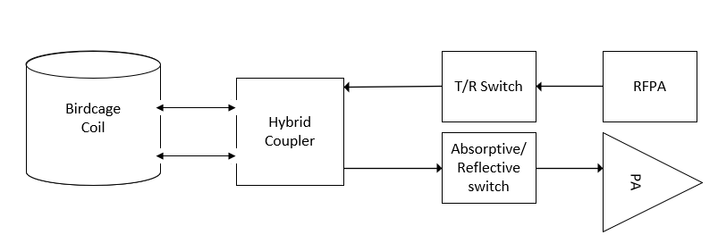
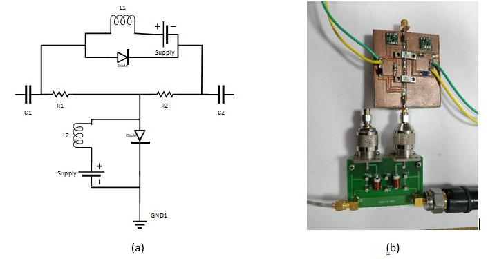
Before going for imaging with quadrature fed birdcage coil, power handling test of the birdcage must be done by interfacing it with the Power Amplifier. Isolation between the two ports of the coil is maximized by tuning the coil and introducing a hybrid coupler. However, to further reduce the RF leakage signal in order to protect the receiver front end, switches in the receive path play an important role. Reflective switch when used causes impedance mismatch at the coupler port which in turn affects the return loss at other ports of the coupler. An absorptive switch when used in the receive chain ensures the impedance matching at the coupler’s receive port and also at the coil ports. Fig 1. Depicts the entire chain of operation. Fig. 2(a)is the circuit diagram of absorptive switch with capacitors acting as dc blocks and the inductors as chokes and Fig. 2(b) is the actual setup of the hybrid coupler with the absorptive switch. The values of the capacitors used are 22nF and chokes of value 10uH. PIN diodes used are from series UM9995 along with two high watt 50Ω resistors.Results
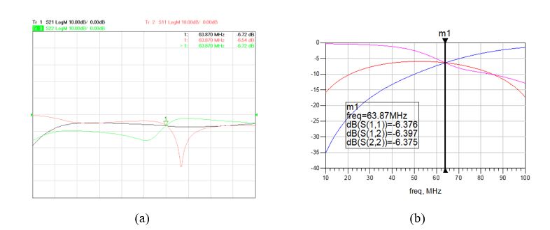
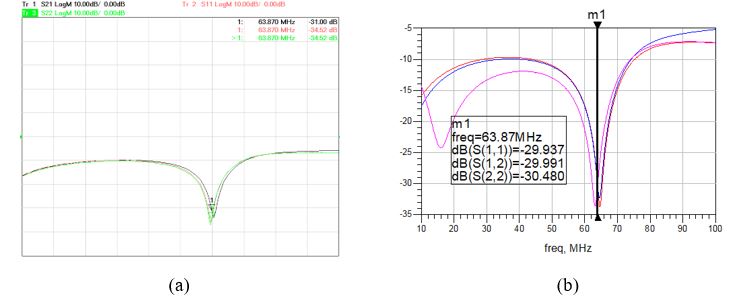
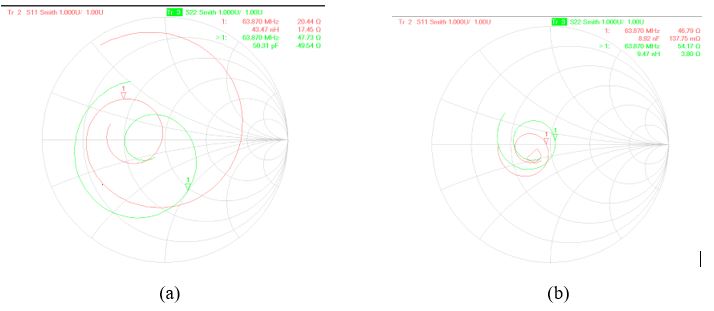
Fig. 3. and Fig. 4. shows the result of the hybrid coupler when the receive port is connected to a reflective switch and an absorptive switch respectively. Fig. 5. Shows the measured impedances on the smith chart for the ports of the coupler which will be connected to the coil.Discussion
Fig. 3. Are the obtained results with the reflective switch which shows that both the return loss (6.54 dB, 6.72 dB) and isolation (6.72 dB) are less indicating impedance mismatch. Fig. 4. Shows the results with the absorptive switch with better return loss (34.52 dB, 34.52 dB) and isolation (31 dB). Fig. 5. Shows the results of impedance mismatch at the hybrid ports (20.4+j17.4Ω, 47.7-j49.5Ω) with the reflective switch and matched impedance at the hybrid ports (46.8-j0.13Ω, 54.1+j3.8Ω) with the absorptive switch. From the above results, it shows that the measured and simulated results are in good agreement for both absorptive as well as reflective switch. However, there is some deviation in the measured and simulated results attributed to the losses of the components such as resistors, inductors and capacitors in the circuit which are not considered in the analysis.Conclusion
Absorptive switch was designed, implemented and further interfaced with the hybrid coupler and ensured that there is no impedance mismatch between the coil and the hybrid coupler. The chosen design also makes sure that the return loss and the isolation between the coil ports are maintained throughout the operation. Simulated results were then compared to the measured results and good agreement was observed between them. From the above results, it has been verified that the chosen switch design will maintain the impedance matching at the coil ports. It is expected that the chosen design will enhance the SNR.Acknowledgements
We would like to thank Sir Joel Mispelter for his valuable discussion.References
1. J. Mispelter et al., “NMR Probeheads for biophysical and Biomedical Experiments”, published by Imperial College Press, 2nd Edition, 2015.
2. Bijaya Thapa et al., “Design and Development of a General-Purpose Transmit/Receive (T/R) Switch for 3T MRI, Compatible for a Linear, Quadrature and Double-Tuned RF Coil”, in Concepts Magnetic Resonance Part B (Magnetic Resonance Engineering) Vol. 46B(2) 56–65 (2016).
3. A M Street, “RF Switch Design”, in IEE Training Course How to Design RF Circuits 6th Aug 2000.
Figures