4274
3D Printable, Floating Cable Trap1Weldon School of Biomedical Engineering, Purdue University, West Lafayette, IN, United States, 2Basic Medical Sciences, Purdue University, West Lafayette, IN, United States, 3School of Electrical & Computer Engineering, Purdue University, West Lafayette, IN, United States
Synopsis
Undesired common-mode currents traveling along the shield of cabling can affect radiofrequency coil performance and cause patient burns. Cable traps are necessary to suppress these common-mode currents in Magnetic Resonance environments. Floating cable traps, which allow for repositioning and reuse and eliminate the need to solder directly to cabling, have previously been reported as custom-manufactured apparatuses1. To streamline the manufacturing of floating cable traps and reduce manufacturing cost, we have designed 3D-printable versions that only require the addition of copper circuitry (e.g., tape/PCB) and lumped elements.
Introduction
Common-mode currents flow along the length of the shield of a coaxial cable. These shield currents can adversely affect performance of Magnetic Resonance Imaging (MRI) radiofrequency (RF) coils by affecting coil decoupling and tuning1,2. This lowers the coil performance and decreases image quality. Further, a hazardous consequence to the patient can be surface burns. There are several current trap designs. The most common are the floating bazooka balun, tank circuits, and ferrite cores3. Aside from the ferrite core method, the bazooka balun and tank circuit require soldering the trap directly to the coaxial cables, making it tedious to remove and reuse (Fig. 1). Similar to a clamping ferrite core, a floating current suppression trap was created by Seeber et al1. This design is fully removable and can be maneuvered along the length of the cable to find the critical placement point for best suppression of common-mode currents. Derivative of this work, we have developed a 3D-printable floating cable trap that allows for quick and consistent manufacturing. 3D printing is a cost-effective means of manufacturing cable traps and, with simple modifications of the inner and outer diameters of the cable trap body and capacitance values, this design can be used for single cables or cable bundles.Methods
The capacitance and inductance of the cable trap were calculated using the following equations for two concentric cylinders:$$L=\frac{\mu}{2\pi}ln\frac{b}{a}$$
$$C=\frac{2\pi\epsilon}{ln(\frac{b}{a})},$$
where L is the inductance of the cylindrical body formed (H/m), µ is the absolute permeability, a is the radius of the smaller cylinder, b is the radius of the larger cylinder, C is the capacitance of the cylindrical body (F/m), and ϵ is the absolute permittivity of the 3D printing filament1,4. For this design, made to fit two RG-58 coaxial cables, the inner radius was 5 mm, the outer radius was 17.88 mm, and the body length was 70.3 mm. The outer diameter was based on the desired number of traces and trace width of the printed circuit board (PCB) balun ends. Similar to our initial prototypes, the cylindrical halves were separated with a spring-nut mechanism5. This allowed for controlled separation of each half to fine-tune the inductance and subsequent matching and tuning. The cylindrical halves, springs, nuts, and screws were all manufactured using PLA filament and natural PVA support material of a desktop 3D printer (Ultimaker 3 Extended, Ultimaker, Geldermalsen, Netherlands). PVA has a dielectric constant of 2.6. The PCB trap ends were designed to connect the outer and interior surfaces of the body, which were both covered in copper tape. All copper tape overlaps and connections to PCB traces were soldered. PCB boards were milled (ProtoMat E44, LPKF, Garbsen, Germany) and super glued to the ends of the body. To accommodate future dual-tuning work, a center trace was added to serve as a pad for anchoring components. The 3D printed components with the PCB boards and copper tape can be seen in Fig. 2. The completed cable trap with the spring-nut system assembled can be seen in Fig. 3. Impedance matching was performed using a vector network analyzer (E5071C, Keysight, Santa Rosa, CA, USA) S21 measurement. A 1-meter length of RG-58 coaxial cable was routed and centered between the cable trap and each end of the cable was placed inside two toroidal probes wrapped around a toroidal ferrite core (Fig. 4). This setup was elevated using foam and cardboard supports to prevent coupling to metal components in the benchtop. Capacitor flags (TSD series, Passive Plus, Inc., Huntington, NY, USA) were used to determine the value needed to impedance match and suppress the currents at the desired frequency of 127.74 MHz, the Larmor frequency of hydrogen nuclei at 3T. For this design, four 20 pF capacitors were used, two on each half.
Results
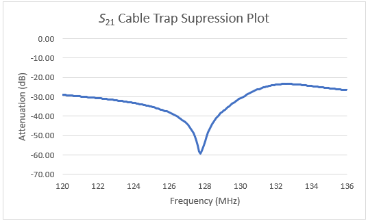
The inherent inductance and capacitance of the 3D printed body was 17.9 nH and 8.77 pF. After 3D printing, the floating cable trap can be assembled quickly. This design was able to be matched and tuned to 127.74 MHz with a spacing distance of 3.52 mm and four 20 pF capacitors. The shield current was attenuated at this frequency by -59.2 dB. The S21 plot can be seen in Fig. 5.Discussion
The lengthiest part of the manufacturing process was 3D printing, taking around 10 hours to complete with a 0.1 mm layer height and 20% infill density. This time could be shortened by reducing the infill density and/or increasing the layer height; however, changing the infill density would alter the dielectric constant of the cable trap body by introducing more air within the PVA material. Milling the PCB, covering with copper tape, assessing capacitor values, and taking measurements can easily be completed in less than an hour.Conclusion
3D printing is a convenient and inexpensive way to consistently manufacture floating cable traps. The cable trap is easily modified to accommodate a custom number of cables and PCB. Since all parts, except for the circuit conductor and components, can be 3D printed, the manufacturing of floating cable traps is streamlined. Because the PCB can be easily modified, our continuing research is to dual-tune this 3D-printable cable trap to accommodate multinuclear MRI and spectroscopy.Acknowledgements
No acknowledgement found.References
1. Seeber, D. A., Jevtic, J. & Menon, A. Floating shield current suppression trap. Concepts in Magnetic Resonance 21B, 26-31, doi:10.1002/cmr.b.20008 (2004).
2. Peterson, D. M., Beck, B. L., Duensing, G. R. & Fitzsimmons, J. R. Common mode signal rejection methods for MRI: Reduction of cable shield currents for high static magnetic field systems. Concepts in Magnetic Resonance 19B, 1-8, doi:10.1002/cmr.b.10090 (2003).
3. Schantz, H. G. The Art and Science of Ultrawideband Antennas. 2nd edn, 177-179 (Artech House, 2015).
4. Harrington, R. F. Time-Harmonic Electromagnetic Fields. (2001).
5. Enríquez, Á. G., Vincent, J. M. & Rispoli, J. V. in 2019 41st Annual International Conference of the IEEE Engineering in Medicine and Biology Society (EMBC). 6802-6805.
Figures