4273
Flexible transmit/receive multi-gap coaxial coils for 7 T MRI1IR4M (Imagerie par Résonance Magnétique et Multi-Modalités), UMR8081, Université Paris-Sud/CNRS, Université Paris-Saclay, Orsay, France, 2Division MR Physics, Center for Medical Physics and Biomedical Engineering, Medical University of Vienna, Vienna, Austria, 3Université de Lorraine, Inserm, IADI, Nancy, France
Synopsis
We propose flexible multi-gap transmit/receive coaxial coils for 7 T MRI with 4, 7, 10 and 15 cm loop diameters, targeting different anatomies with large inter-subject variability and the need for close-fitting coil design. On the bench and in MRI, we evaluate the coaxial coils’ robustness upon bending, compare their performance to standard copper wire coils and demonstrate a significant SNR gain when using form-fitted coaxial coils instead of flat standard coils.
Introduction
At UHF, the use of transmit/receive (Tx/Rx) coil arrays is advantageous to mitigate B1+ inhomogeneities, e.g. with pTx techniques, and to perform accelerated imaging. Form-fitted1 and flexible coils2–6 for 7 T MRI have become one of the hot topics in RF coil engineering. Coaxial coils7,8 are especially interesting as they are lightweight, robust against inter-element coupling6,7 and can be ideally form-fitted to the anatomy of interest, even with large inter-subject variability. In this work, we fabricate flexible coaxial coils (CCs), as described in a previous study9,10, with one or multiple gaps in the inner and outer conductor and four different loop diameters, auto-resonant at the target resonance frequency for 7 T 1H-MRI. On the bench and in MRI, we examine the CCs’ robustness upon bending, their transmit efficiency and SNR performance as compared to standard coils (SCs) made of copper wire.Methods
Coil design and fabrication:Depending on the desired biomedical application, the coil diameter has to be adapted for optimal MR signal Tx and Rx11: 4cm (skin, hand, wrist), 7cm (elbow, ankle, breast, head), 10cm (breast, head, knee) and 15cm (abdomen). While a single-turn, single-gap coaxial coil self-resonant at ≈300MHz would be restricted to a maximum loop diameter of ≈4cm5,10, introducing multiple gaps in the inner coaxial cable conductor and cable shield allows for larger CC diameters whilst maintaining the desired self-resonance frequency. Using an equivalent circuit scheme9, we calculated CC solutions listed in Table 1 with up to 3 gaps and two different cable types that yielded the closest possible self-resonant coil geometries to the target resonance frequency (fLarmor=297.2MHz). The modifiable parameters were the number of cable gaps (ng) and turns (nt), and the coaxial cable type. For comparison purposes, SCs with the same diameters and segmented each ≈λ/10 were fabricated of 1mm copper wire. All fabricated coils including basic interfacing circuitry at the coil port for tuning and matching are shown in Fig.1a and b.
Bench and MRI measurements:
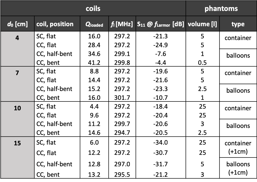
A 5 or 25 l container and holder set-up with a balloon placed on a Teflon sheet shown in Fig.1c were used as phantom loads for bench and MRI measurements, all filled with saline solution (1.6g NaCl/l deionized water, DC conductivity ≈0.2 S/m) and doped with 1ml/l Gd-based contrast agent. Bench and MRI tests were performed with the 4/7/10 cm coils directly placed on/under the phantom, whereas 15 cm coils were placed at 1cm distance. On the bench, SCs and CCs were measured in flat position and CCs in half-bent and bent position. On the bench, the loaded resonance frequency (fl) and the matching level (in dB) were determined with S11 measurements on a vector network analyzer (E5071C, Agilent, Santa Clara, CA, USA). A decoupled double loop probe12 was used to measure the loaded Q factor. Operating the coils in Tx/Rx mode, MR experiments were carried out on a SIEMENS Magnetom 7 T system for flat CCs and SCs as well as bent CCs. B1+ maps normalized to the input power were calculated from flip angle distributions, measured using rectangular pulses of 500μs and adjusted pulse amplitudes per coil diameter to achieve a 90° flip angle in a ROI at ≈d0/4 distance from the coil (25, 63, 130 and 200 V for the 4, 7, 10 and 15 cm coils, respectively). SNR maps were calculated from acquired GRE MR images in the central transversal slice and SNR was evaluated in a circular ROI underneath the coil center (see Fig. 3).
Results and discussion
Bench measurement results in Table 2 show that the stronger the CC bending, the more fl shifts and the matching level at 297.2MHz degrades as the coils were initially tuned and matched in flat configuration; also different phantom sizes were used in bent measurements. Given a specific application, coils would realistically be tuned and matched to a suitable load and the average bending. B1+ efficiency presented in Fig.2 shows good comparability of SCs and CCs of 4/7 cm diameters. The poor matching level of the 4 cm CC in bent position explains the lower B1+ than in flat position. The 7/10/15 cm bent CC measurements indicate robustness and show an increase in B1+/√P when form-fitted to the phantom. SNR maps cropped to the respective coil size are presented in Fig.3. In a circular ROI in flat coil arrangement, depending on the coil size, CCs have comparable or lower SNR than SCs (-8%, -2%, -27%, -36% for d0 = 4, 7, 10, and 15 cm). However, form-fitting the CCs to the phantom compared to the SC in flat position results in a considerable SNR gain (+51%, +46%, +240% and +287% for d0= 4, 7, 10 and 15 cm).Conclusion
We demonstrate flexible multi-gap coaxial coils with 4-15 cm loop diameter made of commercial coaxial cables as Tx/Rx elements for 7 T MRI. In flat configuration, depending on the coil size, CCs show comparable to decreased transmit efficiency and SNR performance as compared to SCs made of copper wire. However, when form-fitted to a phantom, a significant SNR gain as compared to flat SCs is observed for all coil sizes. In future work, we will investigate array configurations and perform SAR simulations.Acknowledgements
This project was funded by the Austrian/French FWF/ANR grant, Nr. I-3618, “BRACOIL“, and Austrian/French OeAD WTZ grant FR 03/2018.References
1. Goluch, S. et al. A form-fitted three channel 31P, two channel 1H transceiver coil array for calf muscle studies at 7 T. Magn. Reson. Med. 73, 2376–2389 (2015).
2. Frass-Kriegl, R. et al. Multi-turn multi-gap transmission line resonators - Concept, design and first implementation at 4.7T and 7T. J. Magn. Reson. 273, 65–72 (2016).
3. Hosseinnezhadian, S. et al. A flexible 12-channel transceiver array of transmission line resonators for 7 T MRI. J. Magn. Reson. 296, 47–59 (2018).
4. Zivkovic, I., Ruytenberg, T. & Webb, A. Highly decoupled shielded loop coils as receive array elements for 7T MRI. in Proc. Intl. Soc. Mag. Reson. Med. 27.1603 (2019).
5. Urayama, S.-I., Zhang, B., Fujimoto, K., Okada, T. & Cloos, M. A. A modular 7T high-impedance array for ex-vivo imaging. in Proc. Intl. Soc. Mag. Reson. Med. 27.1541 (2019).
6. Ruytenberg, T., Webb, A. & Zivkovic, I. Shielded‐coaxial‐cable coils as receive and transceive array elements for 7T human MRI. Magn. Reson. Med. (2019). doi:10.1002/mrm.27964
7. Zhang, B., Sodickson, D. K. & Cloos, M. A. A high-impedance detector-array glove for magnetic resonance imaging of the hand. Nat. Biomed. Eng. 2, 570–577 (2018).
8. Yang, X., Zheng, T., Wu, Y. & Finnerty, M. Coaxial cable magnetic resonance image (MRI) coils. (2017). US patent US9678180B2.
9. Nohava, L. et al. Flexible multi-turn multi-gap coaxial RF coils (MTMG-CCs): design concept and bench validation. in Proc. Intl. Soc. Mag. Reson. Med. 27.565 (2019).
10. Czerny, R. et al. Flexible multi-turn multi-gap coaxial RF coils: enabling a large range of coil sizes. in Proc. Intl. Soc. Mag. Reson. Med. 27.1550 (2019).
11. Kumar, A., Edelstein, W. A. & Bottomley, P. A. Noise figure limits for circular loop MR coils. Magn. Reson. Med. 61, 1201–1209 (2009).
12. Darrasse, L. & Kassab, G. Quick measurement of NMR-coil sensitivity with a dual-loop probe. Rev. Sci. Instrum. 64, 1841–1844 (1993).
Figures