4263
A 16-channel Combined Shielded-Loop-Resonator and Dipole Transceiver Array Design for Body Imaging at 7.0 Tesla1Center for Magnetic Resonance Research, University of Minnesota, Minneapolis, MN, United States
Synopsis
A novel combined shielded-loop-resonator (SLR) and dipole antenna 16-channel transceiver body imaging array (16-SLR-D) is designed by combining eight pairs of dipole antennae and 10x20cm2 SLRs. Performance of the 16-SLR-D is compared against a 16-channel loop-dipole (16-L-D) array through finite-difference-time-domain simulations. Despite the larger loops size and closer placement of the elements, 16-SLR-D design has significantly improved coupling performance with less than 6% power coupled to other channels on average, compared to ~16% of average power coupling of 16-L-D. The combined SLR-dipole array(16-SLR-D) demonstrated ~+15% in transmit efficiency(mT/W0.5), ~+9% in transmit SAR efficiency (mT/SAR0.5) and ~+6% SNR inside the prostate.
Purpose
Goal of this work is to design a 16-channel 7T body imaging array that improves both transmit and receive performance compared to our existing loop-dipole array[1].Introduction
Imaging of the human torso at 7T typically makes use of local transceiver array coils where optimizing both the transmit and receive performance become critical to realizing the potential gains of UHF. On the transmit side, increasing element density, minimizing coupling and maximizing transmit and SAR efficiency become key factors. On receive, SNR is of paramount importance. Combining loops and dipoles have been demonstrated to improve imaging performance inside the body at 7.0T[1] over either resonant structure alone. In the original loop-dipole transceiver array design[1], coupling between neighboring loop elements were mitigated to acceptable levels (e.g. <-10dB) by using smaller-than-ideal loops that are heavily loaded by tissue and physically separated by at least 2cm. Increasing the loop size and bringing the array elements closer to improve performance is not feasible without the addition of decoupling elements, further complicating the design.Shielded-loop-resonators (SLRs) are recently employed in dense array configurations at 3 and 7T and demonstrated excellent coupling performance due to their intrinsic mode of operation[2,3]. In this work, we design a novel combined shielded-loop-resonator and dipole antenna array for body imaging at 7T.
Methods
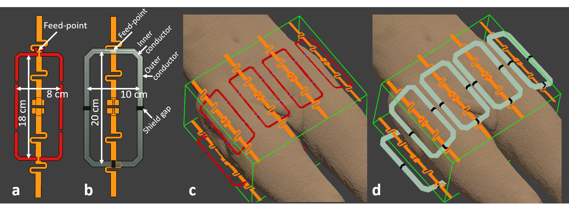
We selected a 10cm loop width for optimal circumferential coverage around the pelvis of an average male, and 20cm length to match the Z-axis field-of-view (FOV) of the fractionated dipole antenna [4], the elements that are paired with SLRs. First, we designed a combined SLR-dipole block by geometrically aligning the SLR and the dipole, then tuning the SLR by optimizing the shape, number and width of the slits. After a SLR-dipole block is designed, we placed eight of these blocks comprising the 16-channel combined SLR-dipole array (16-SLR-D) around the pelvis of the Duke anatomical model[5] with a center-to-center distance of ~11cm, mimicking the geometrical element distribution of the previously developed 16-channel combined loop-dipole array (16-L-D) [1]. A schematic of the loop-dipole block[1] and the new SLR-dipole block are shown in Figure 1.a and b, respectively.Both arrays (16-SLR-D and 16-L-D) were modeled around the pelvis of Duke (Figure 1.c-d). Electromagnetic (EM) field distributions were simulated using the full-wave finite-difference-time-domain solver of Sim4Life (ZurichMedTech, Zürich, Switzerland) and were imported to Matlab (Mathworks, Natick, MA) to investigate transmit and receive performance inside target anatomies of the prostate and bilateral hips, using the numerical methods described herein.
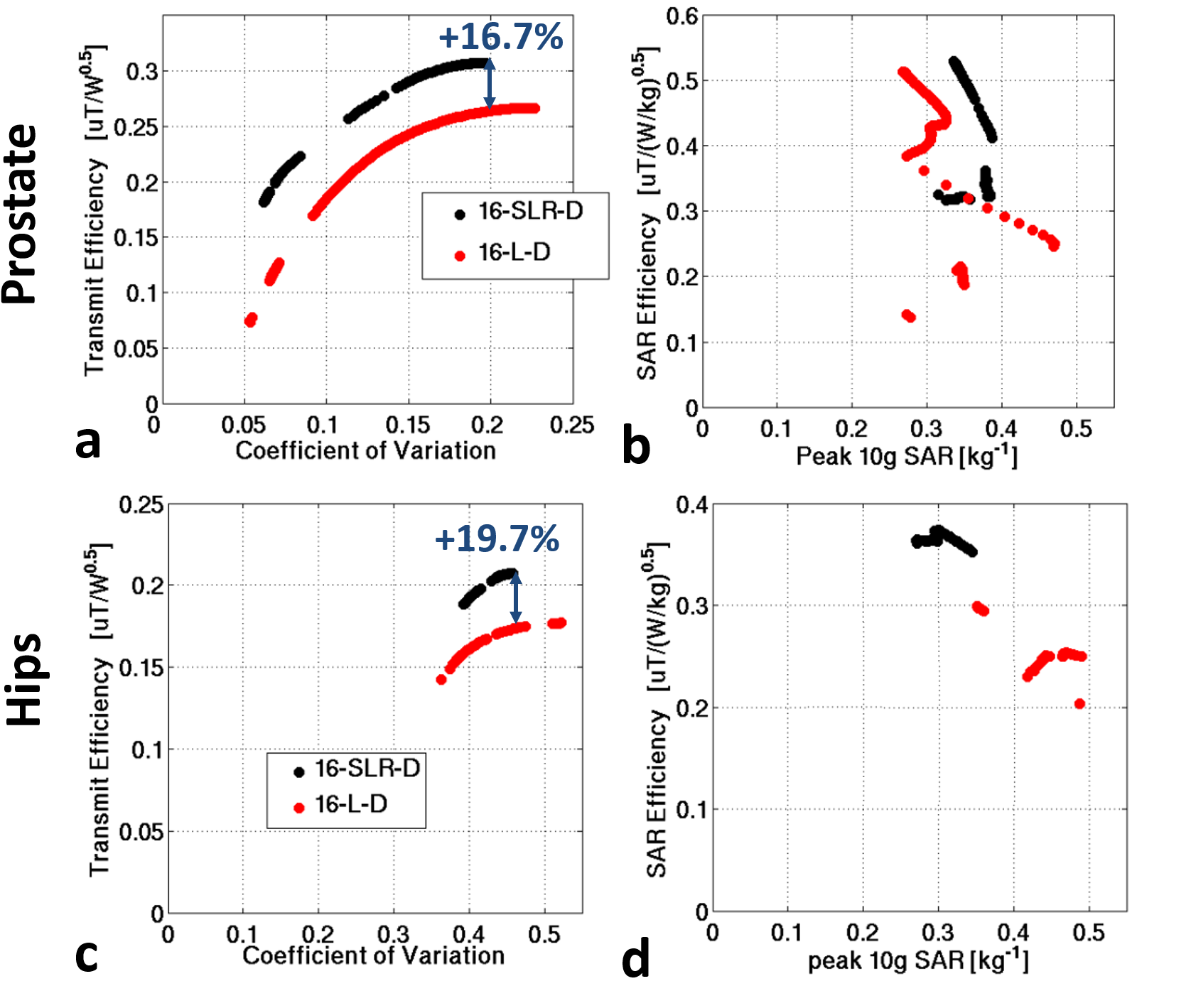
SNR was quantified in a root sum-of-squares fashion inside both anatomies. Phase-only RF shimming [6] yielding peak B1+ efficiency and trade-off solutions between efficiency and uniformity were computed inside both targets; and B1+ transmit efficiency, coefficient-of-variation of B1+ (CoV), peak 10g-averaged local SAR and SAR efficiency performance metrics were evaluated.
Results
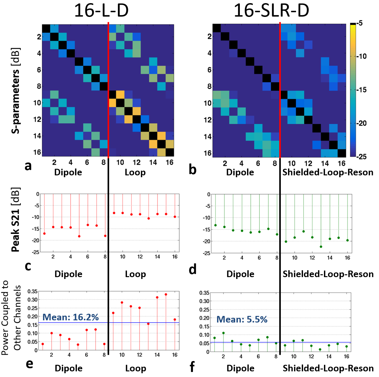
The relatively large size of the rectangular loop required three 6mm-wide slits distributed around the shield with equal distances from each other and the feed-point (Figure 1.b) to tune the SLR at the proton larmor frequency at 7T.Simulated S-parameter matrices with the arrays are positioned around the pelvis are shown in Figure 2.a-b for 16-L-D and 16-SLR-D, respectively. While the highest coupling between neighboring loops can exceed -10dB for the 16-L-D, neighboring SLR elements remained lower than -15dB for the 16-SLR-D despite the larger size (10 vs 8cm width) and closer physical placement of the neighboring elements (Figure 2.c-d). On average ~16% of the accepted power is coupled to other array elements in 16-L-D and less than 6% in 16-SLR-D (Figure 2.e-f).
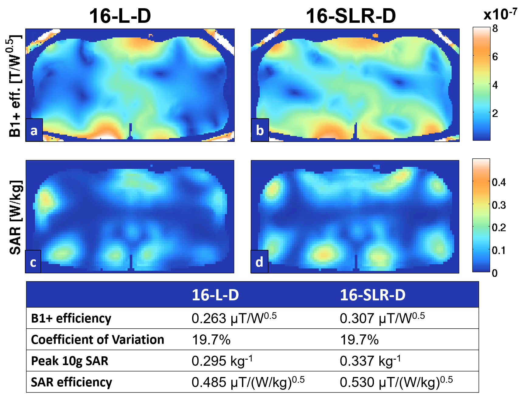
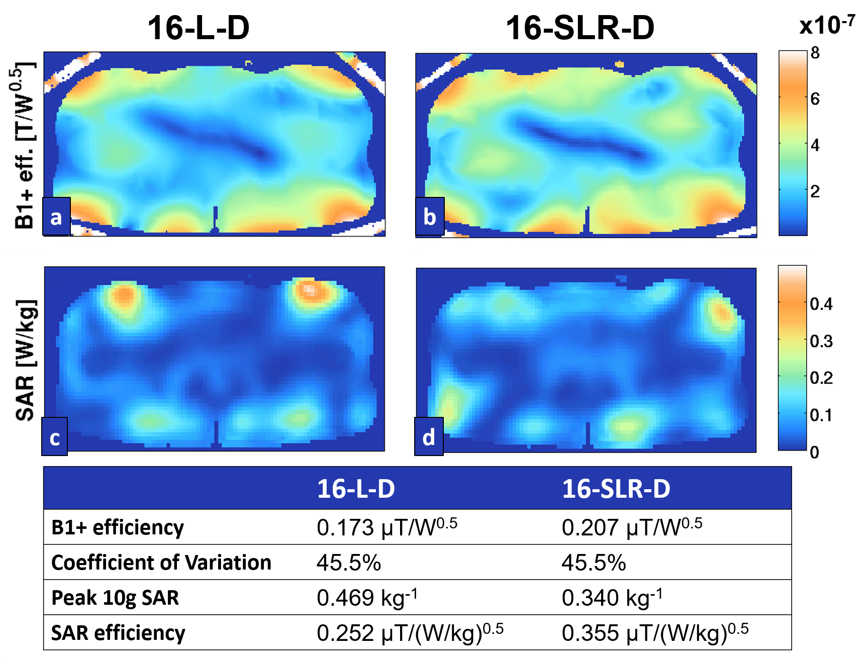
Phase-only RF shimming results targeting B1+ efficiency and trade-off solutions are shown in Figure 3, for the prostate and hips. The 16-SLR-D has >15% higher B1+ efficiency compared to the 16-L-D in both target anatomies. B1+ and 10g-averaged SAR distributions at selected phase-only shim solutions yielding the same field uniformity inside the target anatomies for both arrays are shown in Figures 4 and 5 for the prostate and hips, respectively (left: 16-L-D, right: 16-SLR-D). The 16-SLR-D has 9.3% and 40.9% higher SAR transmit efficiency in the prostate and hips, respectively. Meanwhile, the 16-SLR-D achieves 5.7% higher SNR inside the prostate.
Discussion/Conclusion
SLRs exhibit a significantly better isolation compared to loop coils with similar dimensions, therefore SLR elements are better suited for use in dense array configurations. In this work, we have combined SLRs with dipoles to further increase channel count and designed a 16-channel transceiver array for body imaging at 7T. Use of SLRs enabled us to enlarge the size of the loop elements and permitted a closer physical placement. The new array design (16-SLR-D) improved transmit efficiency by more than 15% inside the prostate and hips compared to a state-of-the art 7T body imaging array (16-L-D) [1] with additional advantages of increased SAR efficiency and SNR.Acknowledgements
Supported by: NIH NIBIB P41 EB027061.References
1. Ertürk MA et al. MRM 2017;77:884-94. DOI: 10.1002/mrm.26153
2. Ruytenberg T et al. (MRM 2019). DOI: 10.1002/mrm.27964.
3. Zhang B et al. (Nature Biomedical Engineering 2018). DOI: 10.1038/s41551-018-0233-y.
4. Raaijmakers AJ et al. MRM 2016;75:1366-74. DOI: 10.1002/mrm.25596.
5. Gosselin M-C et al 2014 Phys. Med. Biol. 59 5287. DOI: 10.1088/0031-9155/59/18/5287.
6. Metzger, GJ et al. MRM 2008;59(2):396-409. DOI: 10.1002/mrm.21476.
Figures