4260
Theoretical Design and Image Reconstruction of an 8-element Receive-only Surface Coil Array for the 1.0 T Australian MRI-Linac System1School of Information Technology and Electrical Engineering, The University of Queensland, Brisbane, Australia
Synopsis
The whole-body coil of the Australian MRI-Linac system can produce images without interfering with the Linac beam during radiotherapy. However, the whole-body coil is distant from the patient, causing lower SNR and is not parallel imaging capable. According to the radiotherapy treatment requirement, an 8-element surface coil array was designed to be radio-transparent and the corresponding imaging algorithms were developed for this coil array. The simulation results showed that the proposed coil array has improved SNR compared to the whole-body coil, and a reduction rate of three can be achieved in parallel imaging without prominent aliasing artefacts.
INTRODUCTION
The 1.0 T Australian MRI-Linac system has a whole-body birdcage coil that is radio-transparent during radiotherapy 1. However, the coil elements of the whole-body coil are distant from the patient, resulting in lower signal-to-noise ratio (SNR) than surface coils. In addition, the whole-body coil is not capable of performing parallel imaging, which is preferred for rapid imaging of tracking targets during MRI-guided radiotherapy. The radiation beam is normally applied within ±45° from the anterior/posterior direction to avoid damage on the contralateral healthy tissue. In this work, we designed an 8-element bilateral surface coil array for the MRI-Linac system, which was conformal to the patient and featuring a window for the radiation beam. However, to arrange these 8 coil elements in such a constrained space, each coil was relatively small, leading to local sensitivity bias on the images reconstructed with sum-of-square (SOS) method. A dedicated image reconstruction and acceleration algorithm employing both GRAPPA 2 and SENSE 3,4 was developed to remove the sensitivity bias. The SNR of the proposed coil array was compared to the whole-body coil and its parallel imaging capability was evaluated with simulations.METHODS
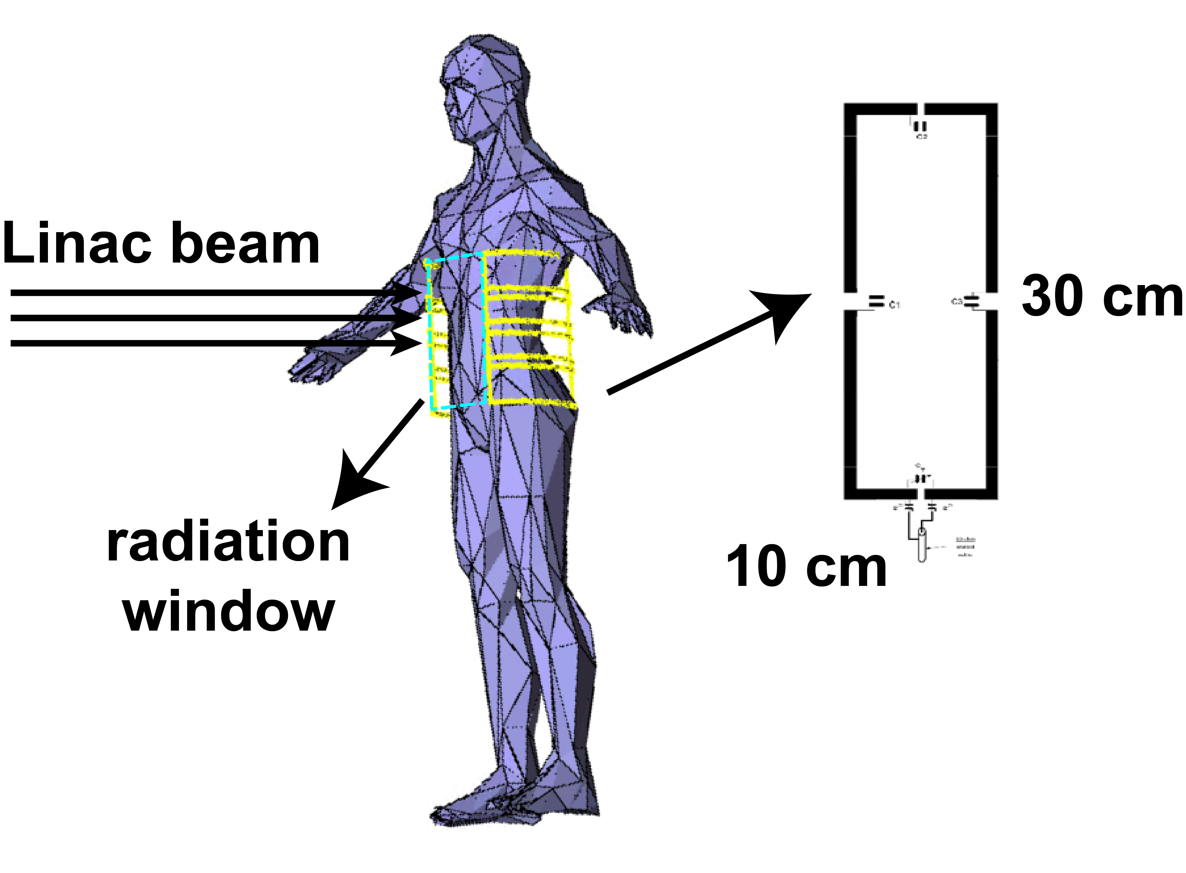
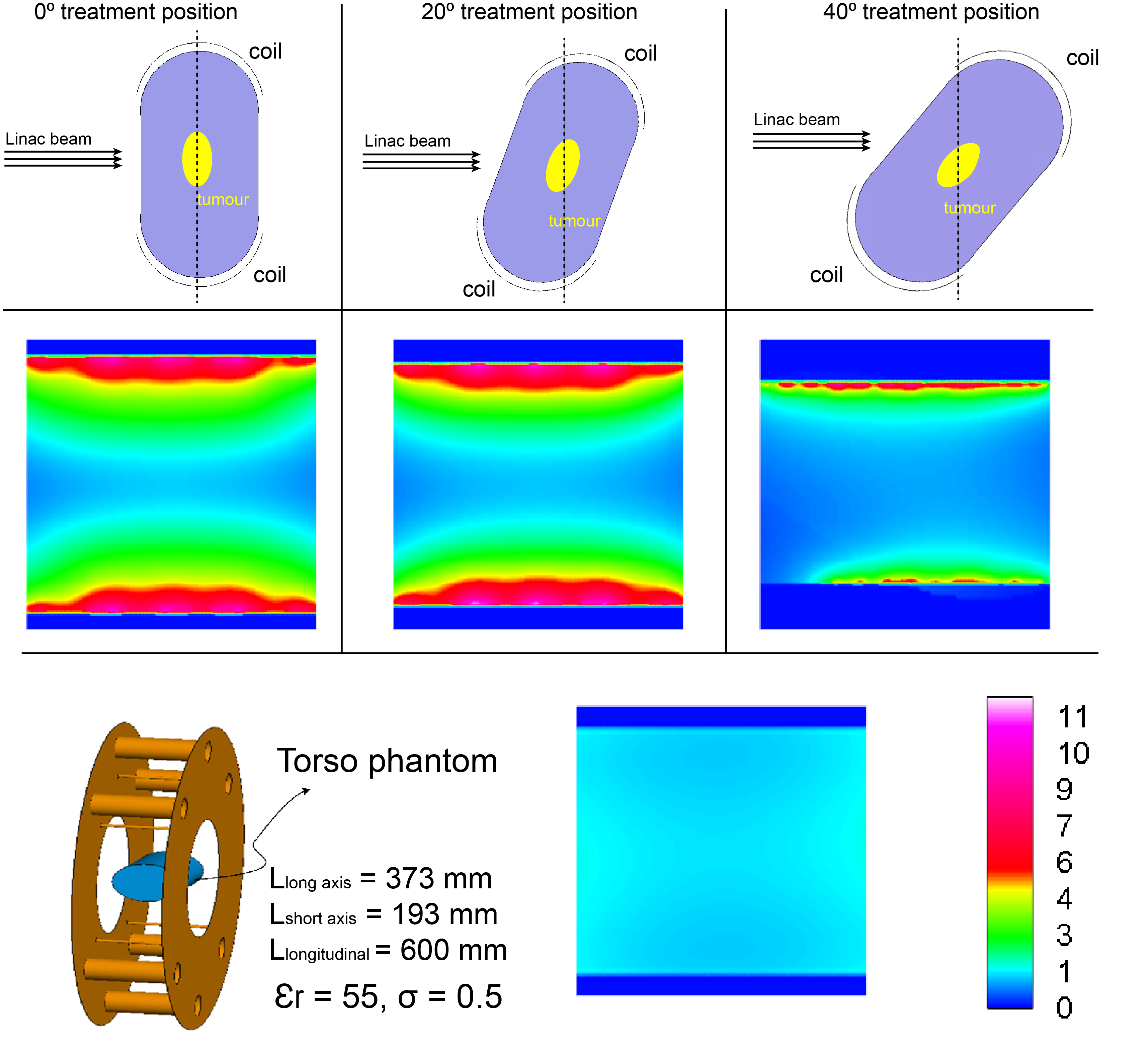
The proposed coil array was designed to accommodate various treatment positions, such as the side-lying position, the standing position and sitting position. For better visualisation of the coils, the standing position in Figure 1 was used to demonstrate the coil patient setup. Four coil elements were placed on each side of the patient. The length and width of the individual coil was 300 mm and 100 mm, respectively. The coils were decoupled with overlapping method. The blue rectangular area between the coils depicts the window to allow the Linac beam passing through without interference with the coils. The whole-body coil was simulated with the same dimension and parameters as described in 1. A torso phantom with electric properties similar to human muscle ( $$$\epsilon_{r}$$$ = 55 and $$$\sigma$$$ = 0.5) was used to load both coils. The longitudinal length of the phantom was 600 mm, the long axis and short axis were 373 mm and 193 mm. The electromagnetic simulation software FEKO (Altair Engineering, Michigan, US) was used to simulate the receive fields. The Matlab (MathWorks, MA, USA) was used to evaluate the SNR and parallel imaging performance. In this work, the same amount of transmission power (8W) was used for both coils. Given the transmission was done by the body coil, transmission profiles were identical for both receive coils, then the SNR was only dependent to the receive field of two coils according to the formula in 5 as:$$\frac{SNR_{array}}{SNR_{body\,coil}}=\frac{|B_1^{-}|_{array}}{|B_1^{-}|_{body\,coil}}$$
where $$$|B_1^{-}|_{array}$$$ and $$$|B_1^{-}|_{body\,coil}$$$ denotes the receive field of the coil array and whole-body coil.
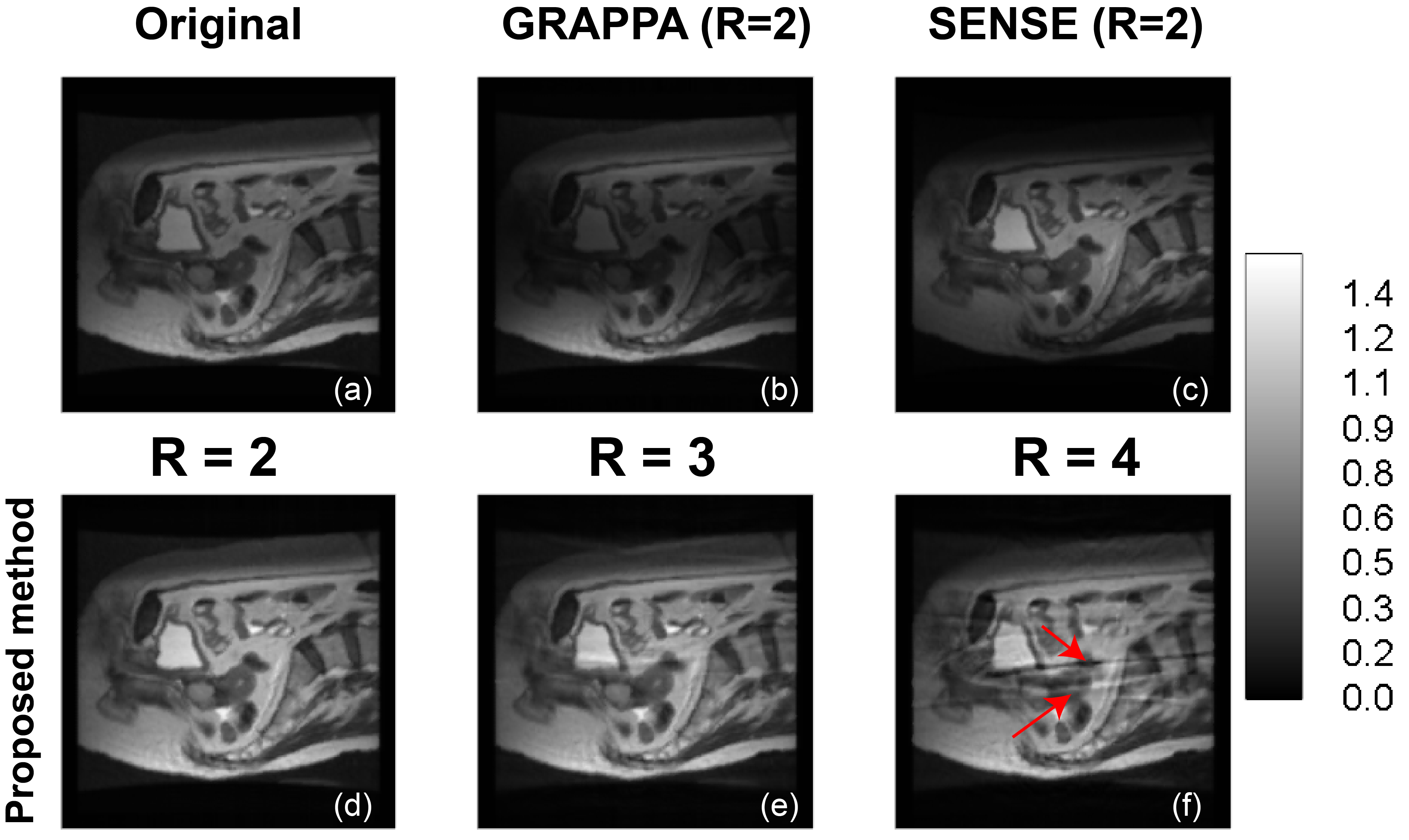
Due to the strong local sensitivity weighting, any imaging algorithm employing the SOS method will be biased by sensitivity profiles, such as GRAPPA in parallel imaging. The signal drop in the image affects clinical diagnosis and undermines its clinical applications. We observed that in the conjugate gradient SENSE (CG-SENSE) algorithm, because of the conjugate operating on sensitivity profiles, the final image could generate opposite sensitivity weightings of the SOS image. Therefore, combining two different contrasts will eventually generate an image with improved sensitivity uniformity.
RESULTS
The coil array was closely-fitted onto the patient and was designed to avoid interference with the Linac beam for different treatment angles. The coil phantom setup (axial plane) and the tumour (yellow region) to be treated are shown in Figure 2. The phantom was repositionable to allow the Linac beams approaching from different angles. SNR in the central slice was evaluated for treatment angles of 0°, 20° and 40° in Figure 2. Compared with the whole-body coil, the proposed array had comparable SNR at the centre of the subject, but about eight times higher SNR at the superficial area. As expected, strong local sensitivity bias was obvious, the centre of the abdomen was dark in Figure 3 (b), when the GRAPPA method was adopted. However, the image restored using the CG-SENSE method (Figure 3(c)) had opposite contrast and can be used to remove the sensitivity bias by combing with the GRAPPA image. In Figure 3 (d) to (f), images reconstructed with the proposed algorithm at different reduction factors (2 to 4) were shown. With a reduction factor of 2, no visible aliasing artefact could be detected; but when the reduction factor was 3, light artefacts were visible. It is noteworthy that in the MRI-Linac, the role of MRI is mainly for radiotherapy guidance; therefore, acquiring high quality images meeting diagnostic standard are less critical. Therefore, light artefacts will not affect tumour tracking. However, when the reduction factor was higher (>=4), the strong aliasing artefact shown in Figure 3 (f) may affect tumour tracking during radiotherapy.DISCUSSION AND CONCLUSION
In this work, an 8-element close-fitted receive-only coil array was designed for the Australian MRI-Linac system. The coil array can provide much higher SNR than the whole-body coil at the surface area and comparable SNR at the central area. The dedicated algorithm can remove the sensitivity bias efficiently and allow the proposed coil array to accelerate imaging up to three times without prominent aliasing artefacts.Acknowledgements
This project is supported by the National Health and Medical Research Council (NHMRC) - The Australian MRI-Linac Program: Transforming the Science and Clinical Practice of Cancer Radiotherapy (1132471)References
1. Liney GP, Dong B, Weber E, et al. Imaging performance of a dedicated radiation transparent RF coil on a 1.0 Tesla inline MRI-linac. Physics in Medicine & Biology. 2018;63(13):135005.
2. Griswold MA, Jakob PM, Heidemann RM, et al. Generalized autocalibrating partially parallel acquisitions (GRAPPA). Magnetic resonance in medicine. 2002;47(6):1202-1210.
3. Pruessmann KP, Weiger M, Bornert P, Boesiger P. Advances in sensitivity encoding with arbitrary k-space trajectories. Magnetic resonance in medicine. 2001;46(4):638-651.
4. Pruessmann KP, Weiger M, Scheidegger MB, Boesiger P. SENSE: sensitivity encoding for fast MRI. Magnetic resonance in medicine. 1999;42(5):952-962.
5. Collins CM, Smith MB. Calculations of B(1) distribution, SNR, and SAR for a surface coil adjacent to an anatomically-accurate human body model. Magnetic resonance in medicine. 2001;45(4):692-699.
Figures