4259
Eight-element Rotating Radiofrequency Coil Array with the Combination of Dipole and Loop Coils for Efficient B1 Shimming and SAR control at 7T1School of Information Technology and Electrical Engineering, The University of Queensland, Brisbane, Australia, 2Siemens Healthineers, Brisbane, Australia, 34. Mark and Mary Stevens Neuroimaging and Informatics Institute, University of Southern California, Los Angeles, CA, United States, 4ARC Training Centre for Innovation in Biomedical Imaging Technology, The University of Queensland, Brisbane, Australia
Synopsis
An 8-element rotating radiofrequency coil array (RRFCA) consisting of loop and dipole pairs is proposed. By placing the dipole coil along the central axis of the loop coil, they are naturally decoupled due to the orthogonality of their polarised fields. Compared with a traditional 8-element static dipole coil array, the RRFCA is designed to provide better B1 shimming and SAR control performance benefited from the physical rotation. In addition, with eight coil elements, SNR will be improved compared to the previously developed 4-element RRFCA.
INTRODUCTION
The rotating RF coil array (RRFCA) is an array of coils that can physically rotate about the subject to transmit and receive signals. With the extra degree of freedom brought by the rotation, the B1 shimming and SAR control ability can be further improved compared with the traditional static coil array. In previous works 1-3, we have demonstrated that a naturally decoupled 4-element RRFCA has better B1 shimming and specific absorption rate (SAR) control performance to shim a large area/volume than a static 8-element loop coil array. However, it was observed that the signal-to-noise ratio (SNR) was penalised by the reduced number of channels. In this work, we propose an 8-element RRFCA combining the dipole and loop coils into pairs, which are naturally decoupled because of their electromagnetic field polarisation. Without the decoupling issue, the large loop coils could be used to improve B1 penetration and decrease the SAR 4. Numerical simulations and optimisation algorithm were used to determine the transmit phases of all coils to improve the B1 field homogeneity and reduce the SAR.METHODS
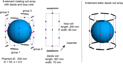
It was shown that natural decoupling can be achieved by placing a dipole along the central axis of a loop coil 4, because of their orthogonal electromagnetic fields. As shown in Figure 1, four groups of such loop and dipole pairs were arranged into an array, separated azimuthally by 90°. The length and width of the loop coils were 200 mm and 80 mm, respectively, and the dipole coils had a length of 267 mm with meanders at both ends. The dipole element was placed 3 mm away from the loop coil. Numerical simulation were performed to investigate the electromagnetic fields of such a hybrid array. An 8-element dipole coil array (Ø: 220) with elements evenly distributed was also simulated for comparison as shown in Figure 1. Coils were loaded with a head-size homogeneous phantom with a diameter of 200 mm, and with a permittivity and conductivity of 55 and 0.5 S/m, respectively. The simulations were performed using electromagnetic software FEKO (Altair Engineering, MI, USA). All fields were calculated with 8W input power for the proposed RRFCA and the static coil array. A custom algorithm was implemented in MATLAB (MathWorks, MA, USA) to optimise the relative phases α between N coils for B1 shimming and SARvoxel minimisation as:$$\mathop{\arg\min_{\alpha}}\mid W_{B1} \cdot\frac{std(B_{1composite})}{mean(B_{1composite})}+W_{SAR}\cdot max(SAR_{voxel}) \mid$$
$$where B_{1composite} = \frac{1}{P}\sum_{n=1}^P|\sum_{n=1}^NB_1^+\cdot exp^{i\alpha_{n}}|$$
$$SAR_{voxel} = \frac{1}{P}\frac{\sum_{n=1}^P\sigma|\sum_{n=1}^NE_{n}\cdot exp^{i\alpha_{n}}|}{\rho}$$
where B1composite is the composition of the time-interleaved B1 field after sampling at all P positions. In this work, RRFCA adopted the stepping mode rotation 2, which transmitted and received the electromagnetic field at 10 positions with 36° increments. The central slice of the phantom was selected as the target area to perform B1 shimming while SAR was controlled over the entire object. WB1 and WSAR are the weighting factors to adjust the balance between the B1 homogeneity and the maximum SARvoxel. σ and ρ are the conductivity and density of the phantom.
RESULTS
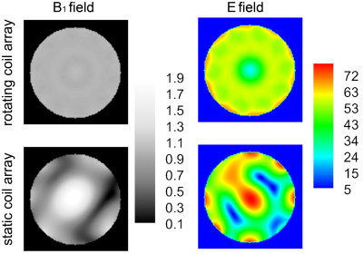
As shown in Figure 2, all coils were well decoupled without using any decoupling techniques. The coupling between loop and dipole coils in the same pair was under -52dB, and the coupling between the loop coil and the dipole coil in the neighbouring group were under -21 dB. The coupling among the four loop coils and among the four dipole coils were around -15 dB. After the phase-only B1 shimming, the static 8-element dipole array had an inhomogeneous B1 pattern (std: 0.39) and the maximum SARvoxel was around 3 W/kg. However, the RRFCA significantly improved the B1 field homogeneity (std: 0.02) while reducing the maximum voxel SAR to 2.4W/kg. As shown in the Table I, the average B1 field of the RRFCA is 14% higher and the maximum voxel SAR is about 12% lower than the static coil array. The SAR efficiency $$$B_1^+/\sqrt{SAR_{peak}}$$$ of the proposed rotating coil array has 28% improvement compared to the static coil array.DISCUSSION
Compared to the continuous rotation, the stepping rotation adopted in this work had more accurate sampling positions, which was important for accurate B1 shimming and SAR minimisation. The previously devolved image reconstruction and acceleration algorithms 2,3 are compatible with the proposed transmission strategy. In the future, the possibility of using continuous rotation for B1 shimming and SAR control will be investigated when combining the previously developed imaging strategies 5,6.CONCLUSION
In this work, an 8-element rotating radiofrequency coil array (RRFCA) was proposed with using pairs of dipole and loop coils. Such a geometric arrangement offered natural decoupling among all coil elements. Facilitated with the extra degree of freedom brought by the physical rotation, the RRFCA can provide better B1 shimming and SAR control performance. In the future, additional numerical studies will be performed with a human head model and further experimental validation will be carried out.Acknowledgements
This project is supported by Australian Research Council Discovery Project - Rotating Radiofrequency Phased-array for 7 Tesla Magnetic Resonance Imaging.References
1. Jin J, Liu F, Trakic A, Weber E, Crozier S, "Application of Rotating RF Coil Array in B1 Shimming with Strict Local SAR Constraints," in ISMRM (International Society for Magnetic Resonance in Medicine), Salt Lake City, USA, 2013.
2. Li M, Zuo Z, Jin J, Xue R, Trakic A, Weber E, Liu F, Crozier S, "Highly accelerated acquisition and homogeneous image reconstruction with rotating RF coil array at 7T-A phantom based study," (in eng), J Magn Reson, vol. 240, pp. 102-12, Mar 2014.
3. Li M, Jin J, Zuo Z, Liu F, Trakic A, Weber E, Zhuo Y, Xue R, Crozier S., "In vivo sensitivity estimation and imaging acceleration with rotating RF coil arrays at 7 Tesla," (in eng), J Magn Reson, vol. 252, pp. 29-40, Mar 2015.
4. Ertürk M, Raaijmakers A, Adriany G, Uğurbil K, and Metzger G, "A 16-channel combined loop-dipole transceiver array for 7 Tesla body MRI," Magn Reson Med, vol. 77, no. 2, pp. 884-894, 2017.
5. Jin J, Weber E, Tesiram Y, Hugger T, Li M, Fuentes M, Ullmann P, Stark S, Junge S, Liu F, Crozier S, "Image Reconstruction for a Rotating Radiofrequency Coil (RRFC) Using Self-Calibrated Sensitivity From Radial Sampling," IEEE Trans Biomed Eng, vol. 64, no. 2, pp. 274-283, 2017.
6. Li M, Weber E, Jin J, Hugger T, Tesiram Y, Ullmann P, Stark S, Fuentes M, Junge S, Liu F, Crozier S, "Radial magnetic resonance imaging (MRI) using a rotating radiofrequency (RF) coil at 9.4 T," , NMR Biomed, vol. 31, no. 2, Feb 2018.
Figures


