4256
An Analytical Study of the effect of RF Chokes on Sensitivity Loss for 'iPRES' Coils at 3T
Yubin Cai1, John Stager1, Hsin-Jung Yang1, Debiao Li1, and Hui Han1
1Biomedical Imaging Research Institute, Cedars-Sinai Medical Center, Los Angeles, CA, United States
1Biomedical Imaging Research Institute, Cedars-Sinai Medical Center, Los Angeles, CA, United States
Synopsis
Introduction
Integrated Parallel Reception, Excitation, and Shimming (iPRES) technology introduces active B0 shimming capability into conventional receive array1-6. To enable simultaneous AC and DC current flows in the shared conductor, the addition of RF chokes or inductors across distributed capacitors on each RF receive loop appears to be inevitable. iPRES coils experimentally shows non-negligible SNR loss, compared to its conventional counterpart3. The novelty of this work is that it provides coil designers with a quantitative and analytical explanation on how these added chokes would impact the coil quality factor and the SNR.One appealing feature in iPRES coil implementation is that a traditional array can be simply modified by adding RF chokes2,3. The added RF choke is to pass DC current while blocking AC current. RF choke has a large impedance and is often neglected for AC analysis. An equivalent circuit model of a RF choke is comprised of an inductor and an equivalent series resistor (ESR). Frequency-dependent and component-specific ESR characterizes the loss in an actual inductor component. Electromagnetic field simulation software, CST®, is utilized. Two 10-cm-diameter iPRES coils are illustrated with 1uH and 300nH self-shielded toroidal RF chokes respectively. Furthermore, the CST simulated Q is investigated with an equivalent circuit analysis.
Methods
The coil Q characterizes a coil’s stored energy relative to the energy lost per cycle and can be numerically expressed as7,$$ Q[ S_{11} method] = \frac{2\omega_0}{\Delta\omega_{+3dB}} \textrm{ <or> } Q[ S_{12} method] = \frac{\omega_0}{\Delta\omega_{-3dB}} $$
Where $$$ \omega_0 $$$ is the resonant frequency. There are two methods to extract Q due to reciprocity between the transmission and the reception of antennas: 1) S11 method, where $$$ \Delta\omega_{+3dB} $$$ is the bandwidth between the +3dB points on the S11 plot and 2) S12 method, where $$$ \Delta\omega_{-3dB} $$$ is the bandwidth between the -3dB points on the S12 plot. Q of an iPRES coil in and out of the presence of a phantom, $$$ Q_{loaded} $$$ and $$$ Q_{unloaded} $$$ respectively, can lead to a numerical prediction of the coil’s signal sensitivity,
$$ SNR = SNR_0 \cdot \sqrt{1 - \frac{Q_{loaded}}{Q_{unloaded}}} $$
Where $$$ SNR_0 $$$ is the total available intrinsic SNR. Thus, by comparing Q ratio ($$$ =\frac{Q_{unloaded}}{Q_{loaded}} $$$) of two coils, the relativity of the SNRs can be determined.
The simulation setups in CST are shown in Fig. 1. The phantom simulated (20-cm-diameter, 17-cm-depth) has a conductivity of 1.109 S/m and relative permittivity of 72.84 at 123MHz. Further, the Q performance is investigated through a circuit-level S11 analysis, based on the circuit diagram shown in Fig. 2. The inductance and resistance of the coil are derived through classic analytic solution of loop antenna’s impedance8. The ESR and the reactance of the toroidal chokes are based on the CST simulation. Last but not least, a circuit-level re-optimization of the unloaded coil Q is derived with respect to ESR and different levels of choke inductance.
Results
Simulated unloaded and loaded Q through CST simulation are reported in Fig. 3. Unloaded Q of iPRES coils are less than that of the traditional coil. With 1uH chokes, the unloaded Q is larger than that of the coil with 300nH chokes. With the phantom modeled in CST, $$$ Q_{loaded} $$$ does not significantly change among the three cases, although it has an inverse relation compared to the $$$ Q_{unloaded} $$$. Fig. 4 shows the re-optimization with respect to a range of ESR and a number of choke inductances.Discussion and Conclusion
CST provides a numerical simulation of ideal electrodynamic scenarios. It reveals, with a user-defined setup, the true coil signal sensitivity in free space. In measurement, however, factors such as environmental noise, loading affects and equipment precision arise and contribute to a discrepancy in absolute Q values between simulation and measurement. The simulated $$$ Q_{unloaded} $$$ of the traditional and the iPRES coil have a trend consistent with the observation in the measurement. Conceptually, despite noise dominance of the phantom, we expect to see coils with different unloaded Q have different loaded Q, which agrees with CST results.Fig. 4 provides coil engineers with a clue to consider the choke effect on iPRES coils. It can be observed that if ESR is equal to zero meaning chokes only store energy rather than dissipate, then the less $$$ L_{choke} $$$ is, the higher overall Q is; if ESR is nonzero, then the reverse is true. Intuitively, the overall coil Q is affected by how much current flows through the ESR in chokes. Maneuvering through the plot in Fig. 4 is not as freely as it might seem. Inductance of a choke is determined by many factors including the length of the conductor, coupling between turns, and geometries. Thus, although a 1uH choke seems to have an optimal Q, a poorly designed 1uH choke with ultra-high ESR might have a Q lower than that of a choke with less inductance. It is important to appreciate the trade-offs during the choke design phase. iPRES alike coils has been a rising topic and analytical work is helpful to understand such novel coils. Future work may include the effects of DC wiring, comprehensive Q and SNR evaluation, bench and scanner measurements.
Acknowledgements
Thanks to Xiaoming Bi, Fei Han, Bernd Stoeckel, Fraser Robb and Miguel Navarro for their support.References
- Han H, Song AW, and Truong TK. Integrated parallel reception, excitation, and shimming (iPRES). Magn Reson Med 2013;70:241–247.
- Truong TK, Darnell D, and Song AW. Integrated RF/shim coil array for parallel reception and localized B0 shimming in the human brain. NeuroImage 2014;103:235–240.
- Stockmann J, Witzel TP, Keil B, et al. A 32-channel combined RF and B0 shim array for 3T brain imaging. Magn Reson Med 2016;75:441–451.
- Twieg M, Mehta B B, Coppo S, Zhu H, Petropoulos L, Fujita H, and Griswold M A. Compact iPRES coil assembly for Magnetic Resonance Fingerprinting. ISMRM 2017.
- Topfer R, Starewicz P, Lo K‐M, et al. A 24‐channel shim array for the human spinal cord: Design, evaluation, and application. Magn Reson Med. 2016;76:1604–1611.
- Winkler SA, Stockmann JP, Warr PA, et al. Comparison of new element designs for combined RF-shim arrays at 7T. Proc. Intl. Soc. Mag. Reson. Med. 23 (2015) p0860.
- Vaughan J T, and Griffiths J R. RF Coils for MRI. Wiley Online Library, 2012.
- Balanis C A. Antenna Theory Analysis and Design. Wiley Online Library, 2005.
Figures
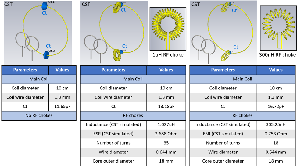
Fig. 1. CST simulation setups with tabulated
parameter values of conventional coil and two iPRES with same main coil
dimensions but different RF chokes, 1uH and 300nH. Both toroidal chokes share the same 18-mm outer diameter
and 0.644-mm wire diameter. AWG 16 and 18 copper wires are used for the
main loop and the chokes, respectively. A double S12
probe is positioned 5 cm away from the coil plane to obtain S12.
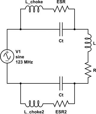
Fig. 2. Equivalent circuit model of iPRES coil
with RF chokes. L and R in the diagram comprise the coil impedance.
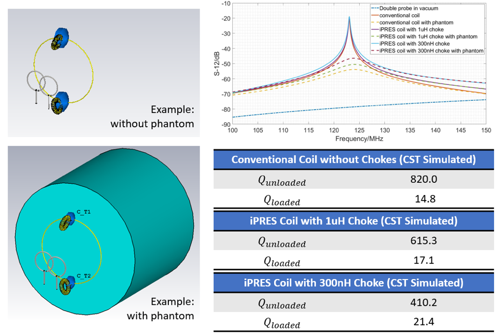
Fig. 3. CST simulated S12 of iPRES coils with a 1uH
or 300nH RF choke in or out the presence of the phantom. The extracted unloaded and loaded quality
factors are shown in the tables.
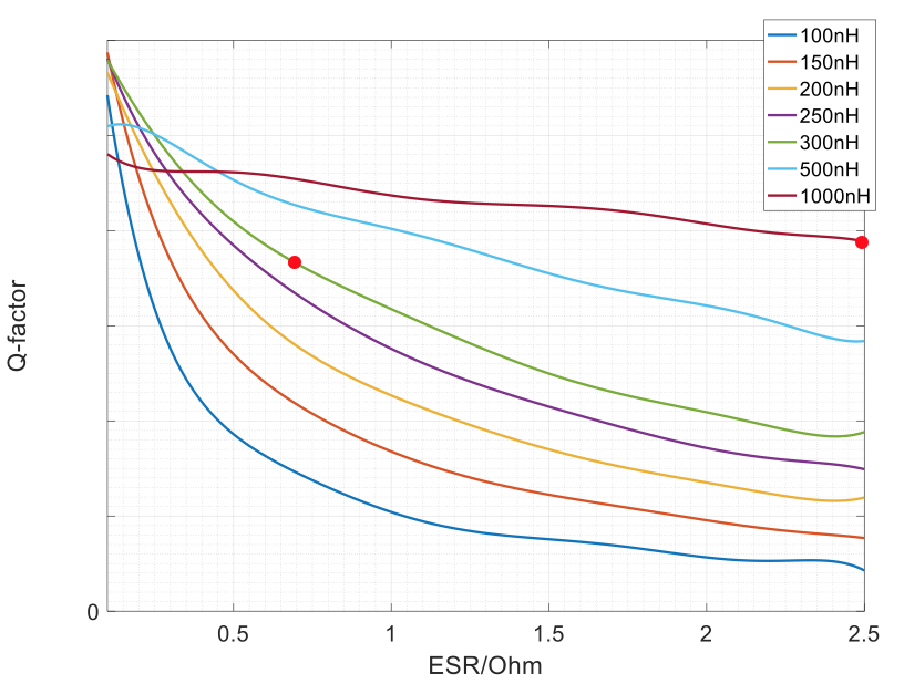
Fig. 4. Unloaded quality factor of iPRES coil with
respect to the ESR in the RF choke with different levels of choke inductance
values shown in the legend. Results are generated through circuit-level analysis. The red data points correspond to the two
illustrated iPRES coils that are studied through CST simulation and circuit
analysis.