4255
Design and simulation of a transmit coil system for human head and neck imaging at 5 T1Shenzhen Institutes of Advanced Technology, Chinese Academy of Sciences, Shenzhen, China, 2Shanghai United Imaging Healthcare, Shanghai, China, 3Department of Biomedical Engineering, State University of New York, Buffalo, NY, United States
Synopsis
To achieve high SNR and high contrast for human MRI, ultra-high field can be applied. Considering the safety issues and the inhomogeneity of images at high fields, we aim to build a 5 T whole body MRI system. Based on this system, a transmit coil system for human head and neck imaging is designed and simulated. This work shows the preliminary studies with B1+ field and SAR assessments at 5 T.
Introduction
Ultra-high field human magnetic resonance imaging (MRI) has been developed rapidly in recent years and it is of great significance in the human brain studies [1]. For clinical applications and research in high resolution imaging, 7 T human MRI is extremely useful. However, 7 T systems involve more technical challenges and also are more expensive in comparison with 3 T system. Moreover, due to physical constraints, radio frequency (RF) wavelength operating at 7 T is too short, which may cause some safety problems and inhomogeneous images [2]. Multi-channel transmitting coils with independent time-varying amplitudes and phases are the key to obtaining high quality images for 7.0 T MRI systems, but their supervision is drastically more complicated, especially due to a stronger dependence on the individual patient anatomy [1]. Considering the issues above, we aim to build a 5 T whole body MRI system, which can not only provide high signal-to-noise ratio (SNR) and high contrast for imaging, but also reduce the specific absorption rate (SAR) of energy for human and the inhomogeneity of images. In this work, we designed and simulated a transmit coil system for human head and neck imaging. Firstly, the simulated B1+ field homogeneity inside a phantom for the only birdcage coil driven in circular polarization excitation (CP+) mode at 3 T, 5 T and 7 T was compared. The B1+ field and the SAR distribution of the transmit coil system at 5 T were evaluated inside a human body model.Methods
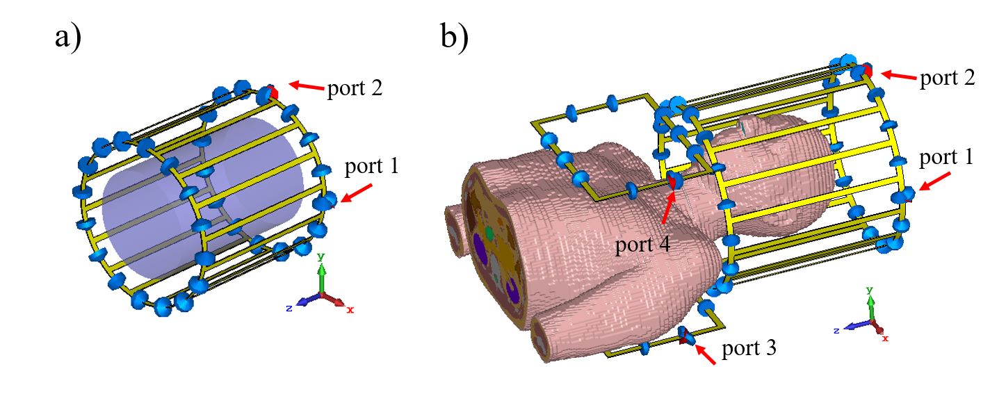
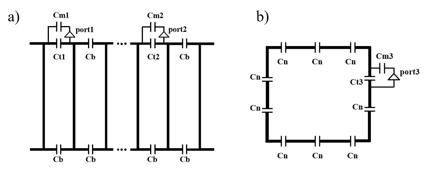
The simulation prototypes are shown in Fig. 1. For human head imaging, a high-pass birdcage coil with a diameter of 300 mm and a length of 310 mm was designed. The number of legs was chosen as 16. The diameter and the length of the coil shield were both 360 mm. For neck imaging, a Helmholtz coil with sizes 202 mm × 290 mm in rectangle shape, of which coil shield also in rectangle shape with the same sizes was 10 mm away from the coil. The distance between Helmholtz coil pairs was 286 mm and the gap between the birdcage coil and the Helmholtz coil was 10 mm. To avoid interference between the Helmholtz coil and the birdcage coil shield, the end of the birdcage coil shield near the neck part was aligned with the end of the birdcage coil. Simulations were performed with the Finite-Integration Time-Domain Method (Microwave Studio, CST, Darmstadt, Germany). The phantom was a cylinder with a diameter of 100 mm and a length of 300 mm, of which parameters were set as conductivity = 0.6 S/m, relative permittivity = 83. The human body model used the “Gustav” model from the virtual family. The circuit schematics of the transmit coil system are depicted in Fig. 2. By adjusting the values of the capacitors, the coils were finally tuned to the Larmor frequency and matched to 50 Ohm. In the evaluation of the only birdcage coil performance at 3 T, 5 T and 7 T, the B1+ field homogeneity was defined as: (max-min)/ (2*mean) in the region of interest (ROI). The 10 g average SAR maps inside the human body model for the transmit coil system were calculated based on 1 W of input power.Results
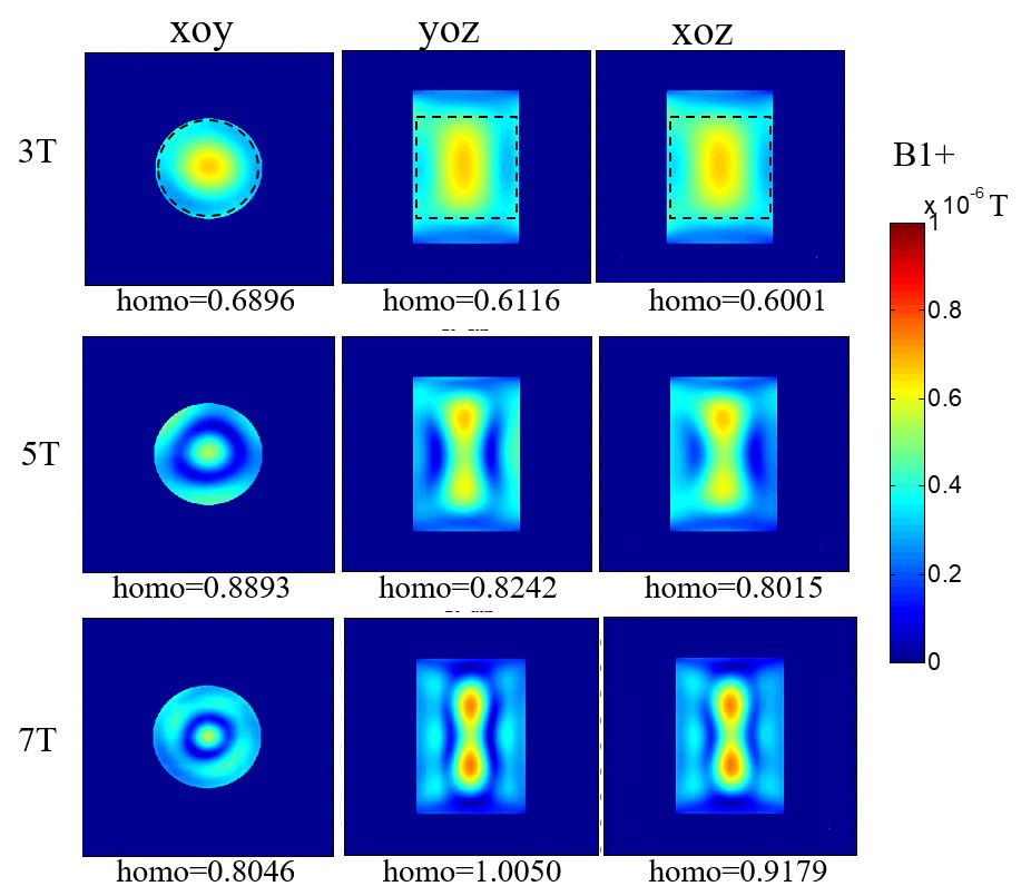
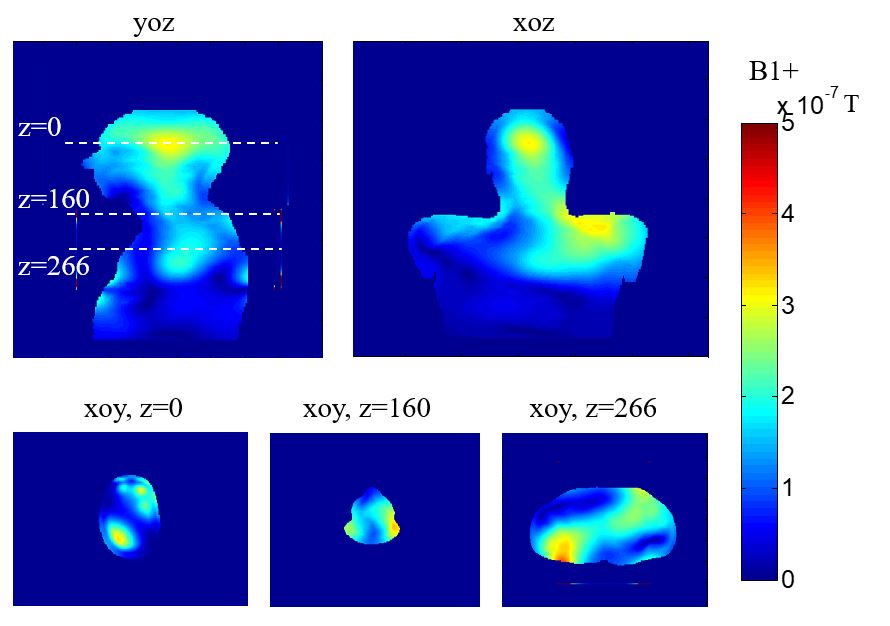
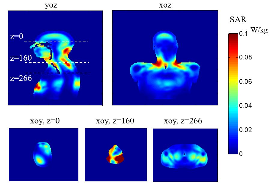
Fig. 3 shows the comparisons of the simulated B1+ field homogeneity inside the phantom for the only birdcage coil at 3 T, 5 T and 7 T, from which it can be known that the B1+ field is more homogeneous when the birdcage coil operates at a lower Larmor frequency. The simulated B1+ maps of the transmit coil system inside the human body model are illustrated in Fig. 4. In this calculation, to achieve a uniform B1+ field, the amplitudes (A) and phases (P) for each port are as following: A1=A2=1, A3=A4=2, P1= P3=P4=0o, P2=90o. Fig. 5 depicts the 10 g average SAR maps. It can be seen that large SAR values appeared at the junction of the head and neck coil. The maximum inside the human body model is 0.261 W/kg.Discussions
In the comparison of the simulated B1+ maps inside the phantom for the birdcage coil only, the field in the yoz and xoz planes at 5 T is more homogeneous than that at 7 T. In the human model simulation, the homogeneity of B1+ field can be further improved by optimizing the amplitudes and phases of the ports. To reduce SAR values at the neck, high dielectric pads can be applied.Conclusion
A transmit coil system including a birdcage coil and a Helmholtz coil for human head and neck imaging at 5 T was designed and evaluated by the electromagnetic field simulations. This work has showed the preliminary studies with B1+ field and SAR assessments. To better apply this transmit coil system at 5 T, further optimization work will be done in the futureAcknowledgements
This work was supported in part by NSFC under Grant No. 61571433, 61801466, 81527901, 81830056; Grant No. 2017YFC0108800; Youth Innovation Promotion Association of CAS No. 2017415; city grant JCYJ20170413161314734.References
[1] E. Moser, E. Laistler, F. Schmitt, and G. Kontaxis. “Ultra-High Field NMR and MRI-The Role of Magnet Technology to Increase Sensitivity and Specificity,” Frontiers in Physics, vol.5, article 33, Aug. 2017.
[2] T. Ibrahim, Y. Hue, and L. Tang. “Understanding and manipulating the RF fields at high field MRI,” NMR in Biomedicine, vol.22, no.9, pp. 927-936, Nov. 2009.
Figures