4254
A novel radiofrequency (RF) coil using dipole with multi-radiating elements at 7T1School of ITEE, The University of Queensland, Brisbane, Australia
Synopsis
At ultra-high field (UHF) MRI, dipole-based antennas have deeper field penetration but increased specific absorption rate (SAR) levels than loop-type coils. In this work, a novel RF coil is proposed based on layer-configured dipole and multiple radiating elements. The designed RF coil is compared with a conventional dipole antenna in electromagnetic simulations and it is observed that more than 30% SAR reduction can be achieved with improved B1+ efficiency.
Introduction
Radiative dipole antennas are widely used in multi-channels transmitting radio frequency (RF) coil designs at ultra-high field (UHF) MRI because of their attractive features, such as the increased field penetration and symmetric field 1-3. However, these advantages are accompanied with drawbacks such as the concentrated $$$B_1^+$$$ field near the surface and high specific absorption rate (SAR) level causing increased risk of RF-induced heating. To reduce the SAR level, a slot dipole array was proposed 4. The slot antenna has a similar radiation pattern compared with its complementary dipole antenna but produces lower SAR distribution and improved $$$B_1^+$$$ efficiency. In this work, a novel RF coil is designed using a dipole antenna with multiple radiating elements. Similarly to slot antennas, the proposed RF coil can significantly reduce the SAR level, but with the advantage of broadening the field distribution and homogeneity of the $$$B_1^+$$$ field distribution.Methods
Inspired by the classic Yagi-Uda antenna array5, multiple radiating elements (MREs) were used in this work to build the novel RF coil. As the MREs divide the coil current distribution into several segments, the radiated electromagnetic (EM) wave and RF energy are evenly distributed, and thus a flattened RF field pattern and reduced SAR level can be achieved. The coil was designed with two layers (Fig. 1C) on opposing sides of a dielectric substrate. The top side of the substrate is a conventional dipole with two inductors, which are used to tune the resonant frequency and reduce its electrical length (Fig. 1A). On the bottom side, a metal structure with five slots enables the MREs, which were passively excited by the conventional dipole (Fig. 1B). The concentrated electric field normally radiated from the dipole can be distributed and re-radiated by the MREs. Because the SAR level is in direct proportion to the electric field intensity, the distributed electric field could significantly reduce the SAR concentration and flatten the RF field pattern. The designed RF coil was fabricated using RO4360G2 substrate and RO4460G2 prepreg with dielectric constant of 6.15 and total laminated thickness of 9.65 mm. The dimensions of the coil were optimized in CST (Microwave Studio, Darmstadt, Germany) to improve the matching of the coil, RF field pattern and SAR level. The design was evaluated using a phantom with tissue-like properties ($$$\epsilon_{b}$$$=34 and $$$\sigma$$$=0.4) (Fig. 1C) and the human voxel model Emma from the bio-model library in CST. The 10g-averaged peak local SAR (SAR10g) and $$$B_1^+$$$ field were used to calculate the $$$B_1^+$$$ efficiency as $$$B_{1;eff}^+=B_1^+/\sqrt{max{SAR_{10g}}}$$$. A conventional dipole antenna with lumped inductors was also simulated for comparison. The coils were tuned to 297 MHz for 7T MRI, with inductor values of 21 nH for the proposed design and 47 nH for the conventional dipole. The specific dimensions of the proposed coil are shown in Fig. 1A-B while the length and width of the conventional dipole antenna are 250 mm and 10 mm, respectively.Results and Discussion
The simulated $$$B_1^+$$$ efficiency and SAR10g distribution in three planes (axial, coronal, and sagittal) are shown in Fig. 2A-B. The $$$B_1^+$$$ field was normalized to 1W of accepted power at the excitation port. It can be seen that the penetration depth with respect to $$$B_1^+$$$ efficiency was improved by using the MREs compared with using a single dipole. The SAR10g was substantially reduced especially close to the surface of the phantom. Figures 3 shows line plots extracted from the dashed lines in Figure 2, to quantitatively compare the designs. It can be observed that enhanced $$$B_1^+$$$ efficiency was achieved particularly at the deeper region of the phantom (100-200 mm away from edges of the phantom). It can also be seen that the SAR10g was reduced at the shallow region of the phantom (maximum local SAR10g was reduced from 1.662 W/kg to 1.235 W/kg on the selected axial plane), where maximum SAR10g is typically present. It is also worth mentioning that the maximum SAR10g in the entire phantom volume was reduced from 1.85W/kg to 1.29W/kg which corresponds to 30.27% reduction. In addition to the comparison of $$$B_1^+$$$ field efficiency, $$$B_1^+$$$ intensity at the central point of phantom using the same stimulated power of 1 W was also compared. Simulation results indicated that the central $$$B_1^+$$$ intensity was 0.182 uT for the conventional dipole while it was improved to 0.19 uT for the MREs coil. The Emma voxel model from CST was further used to evaluate the performance of the proposed coil, and the results are shown in Fig. 4. It can be seen from Fig. 4 that the proposed coil achieved higher $$$B_1^+$$$ efficiency at all the three planes than that of the conventional dipole. The maximum global SAR10g of the proposed coil (1.39 W/kg) had a 58% reduction compared to the conventional dipole (3.3215 W/kg).Conclusion
A novel RF coil was designed using a dipole with multiple radiating elements. Compared with a conventional dipole, $$$B_1^+$$$ efficiency can be enhanced and the SAR10g can be reduced.Acknowledgements
No acknowledgement found.References
1. Raaijmakers AJE, Ipek O, Klomp DWJ, Possanzini C, Harvey PR, Lagendijk JJW, den Berg CAT. Design of a radiative surface coil array element at 7 T: The single-side adapted dipole antenna. Magn Reson Med. 2011; 66:1488–1497.
2. Raaijmakers AJE, Italiaander M, Voogt IJ, Luijten PR, Hoogduin JM, Klomp DWJ, van den Berg CAT. The fractionated dipole antenna: A new antenna for body imaging at 7 Tesla. Magn Reson Med. 2016; 75:1366–1374.
3. Oezerdem C, Winter L, Graessl A, Paul K, Els A, Weinberger O, Rieger J, Kuehne A, Dieringer M, Hezel F, Voit D, Frahm J, Niendorf T. 16-channel bow tie antenna transceiver array for cardiac MR at 7.0 tesla. Magn Reson Med. 2016; 75:2553–2565.
4. Alon L, Lattanzi R, Lakshmanan K, Brown R, Deniz CM, Sodickson DK, Collins CM. Transverse slot antennas for high field MRI. Magn Reson Med. 2018; 80:1233-1242.
5. Yagi H, Uda S. Projector of the sharpest beam of electric waves. Proceedings of the Imperial Academy. 1926; 2: 49-52.
Figures
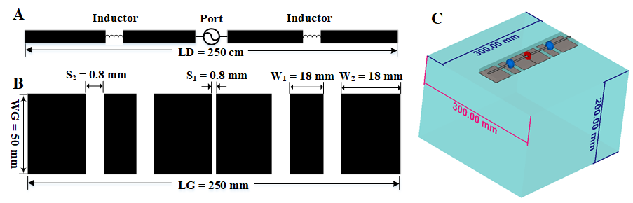
Fig. 1 A: Structure on the top layer. B: Structure on the bottom layer (MREs). C: Three-dimensional model of the proposed RF coil and a homogeneous phantom with length of 300 mm, width of 300 mm and height of 200 mm.
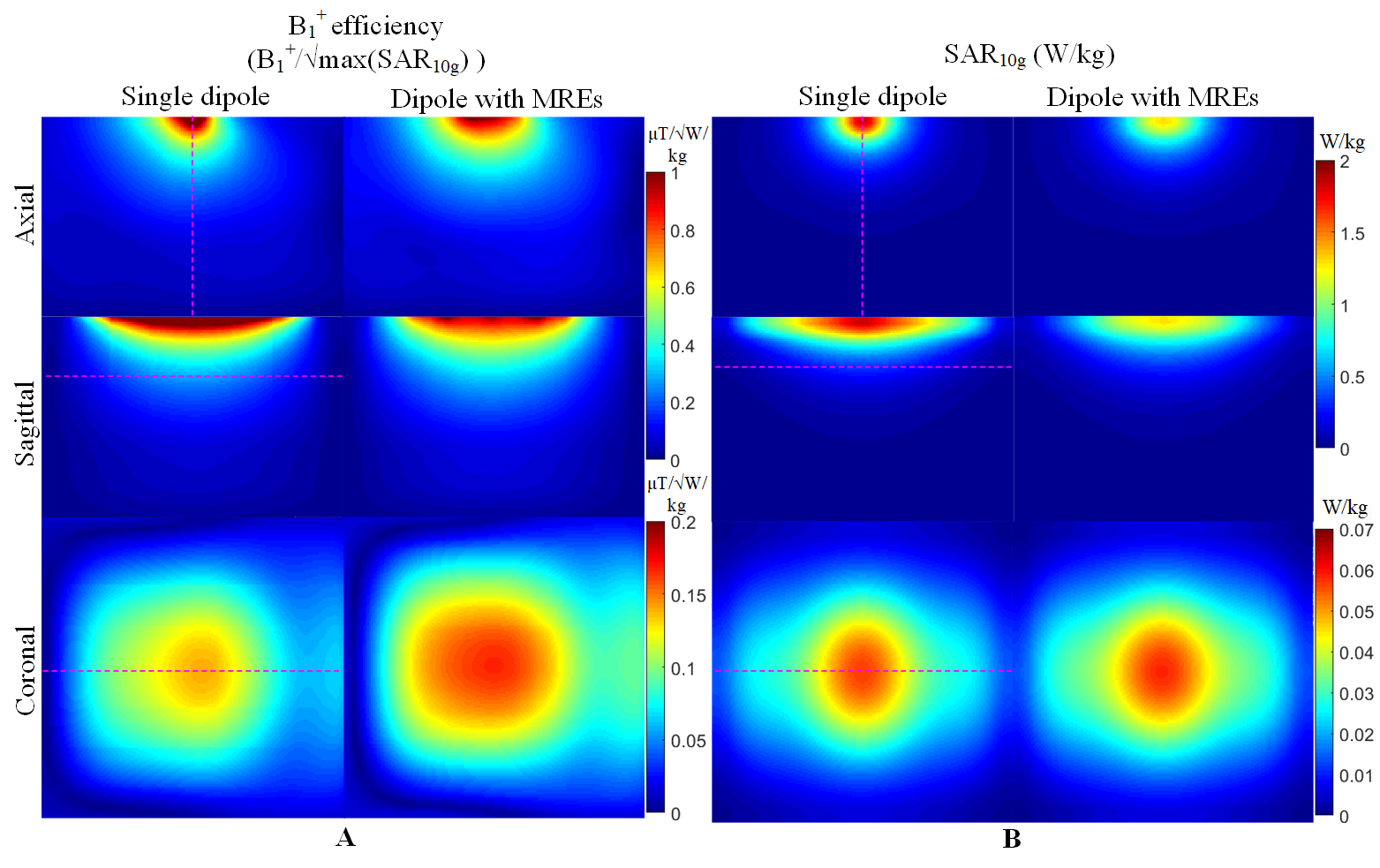
Fig. 2 A: Simulated B1+ efficiency inside the phantom in three planes. B: Simulated SAR10g inside the phantom. The left column of A and B shows the results from using a single dipole and the right column of A and B shows the results from using the dipole with MPE. The axial and sagittal planes are selected to cross the port of the coil, and the coronal plane is selected to cross the centre of the phantom.
*In A, range of colour bar for axial and sagittal planes is 0~1 uT while it is 0~0.2 uT for the coronal plane. In B, it is 0~2 W/kg for axial and sagittal planes while it is 0~0.07 W/kg for the coronal plane.
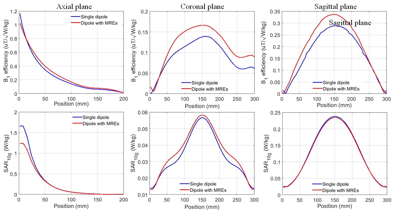
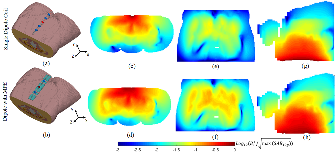
Fig. 4. B1+ efficiency evaluated by using the Emma voxel model from CST. (a)-(b): The dipole and the proposed coil are placed above the abdomen with a distance of 10 mm. (c)-(d): B1+ efficiency distribution at the central axial plane, (e)-(f): central sagittal plane, and (g)-(h): central coronal plane.
*It should be noted that the images were shown in the logarithm scale with the base of 10.