4252
FDTD Simulation of embedded Elongated Conductors: Impact of Voxelization Errors and Model Simplification1Biomedical Engineering Department, School of Biomedical Engineering & Imaging Sciences, King's College London, London, United Kingdom, 2Centre for the Developing Brain, School of Biomedical Engineering & Imaging Sciences, King's College London, London, United Kingdom
Synopsis
Several MRI scenarios can be studied by using electromagnetic simulation tools. The most common EM simulation software requires spatial discretization which can, for narrow objects like elongated conductors, become computationally heavy and time consuming. To avoid that, such objects are typically discretized suboptimally. Here, using FDTD simulations, we explore how these practices can often lead to errors which are not trivial to track and how simple changes in modelling can lead to significatively different results.
Introduction
Electromagnetic Simulations are useful tools to study MRI scenarios. Several methods are in common use to solve Maxwell’s Equations, including the Finite Element and Finite-Difference Time-Domain (FDTD) methods. Numerical simulations of this type require spatial discretization, which is not a problem when modelling large objects that can be accurately meshed on a coarse grid (e.g. human model, RF coil, RF shield, etc.) but quickly becomes computationally heavy and time consuming when modelling finer objects, like elongated conductors, which demand the use of a fine grid. With finer grids, the maximum time-step allowed increases due to the CFL condition1 as well as memory consumption due to the increased number of mesh cells.In an ideal world, all aspects of a model would be meshed accurately, but in practice this often leads to unfeasibly large models. To reduce computation time and memory usage to feasible levels, compromises are generally made, which can lead to voxelization errors and inaccuracies. In this work, we examine some issues that can arise when modelling long thin insulated wires.
Methods
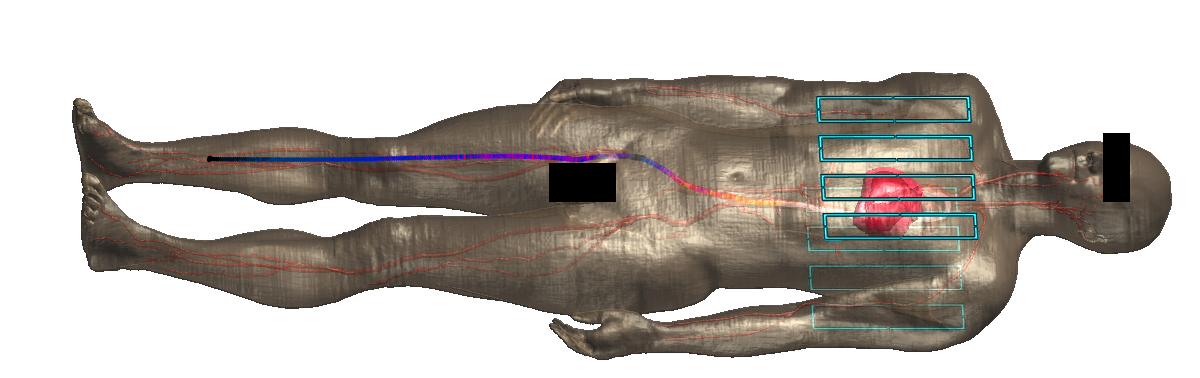
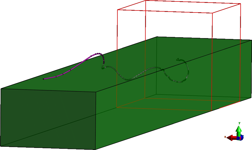
The FDTD solver provided by Sim4Life (ZMT, Zurich, Switzerland) was used to model a realistic cardiac guidewire wire, core (∅ = 1mm - perfect electric conductor - PEC) with an insulation layer of outer radius 1.25mm (distal 5mm stripped). In Fig.1 we can see the layout of a typical human model (Duke (ITIS ViP3.1)) simulation with an elongated conductor, and in this case, an 8-channel Tx/Rx cardiac RF coil, excited at 64MHz, which can serve an example test case.To assess the impact of voxelization errors identified in the Duke model, a set of further simulations were run using the same wire geometry, but embedded within a homogeneous dielectric phantom (ε=60; σ=0.4 S/m), excited using a 64MHz plane wave as the source (Fig.4). The transition from Duke to the dielectric phantom allowed us to simplify the model and focus on the interaction between the wire geometry and the gridding/voxelization while significantly decreasing computational time and memory consumption since the surrounding geometries were much simpler. Three variants were tried:
Simulation 1: 0mm Wire (diameter) - PEC without voxelization issues.
Simulation 2: 0mm Wire (diameter) - PEC with voxelization issues.
Simulation 3: 1mm Wire (diameter) - PEC with voxelization issues.
where the 0mm thick wire is modelled only along edges of the grid, while the 1mm wire is represented as voxels. In all cases the wire was surrounded by an insulator of outer radius 1.25mm as in the previous model. A voxel grid was generated for Simulation 1 and visually checked to ensure that there was no risk of exposed conductor and was then enforced on Simulations 2 and 3.
Results & Discussion
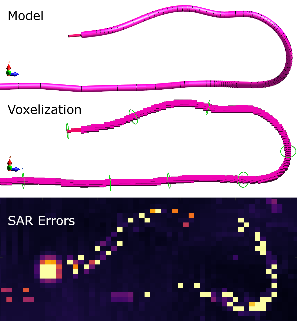
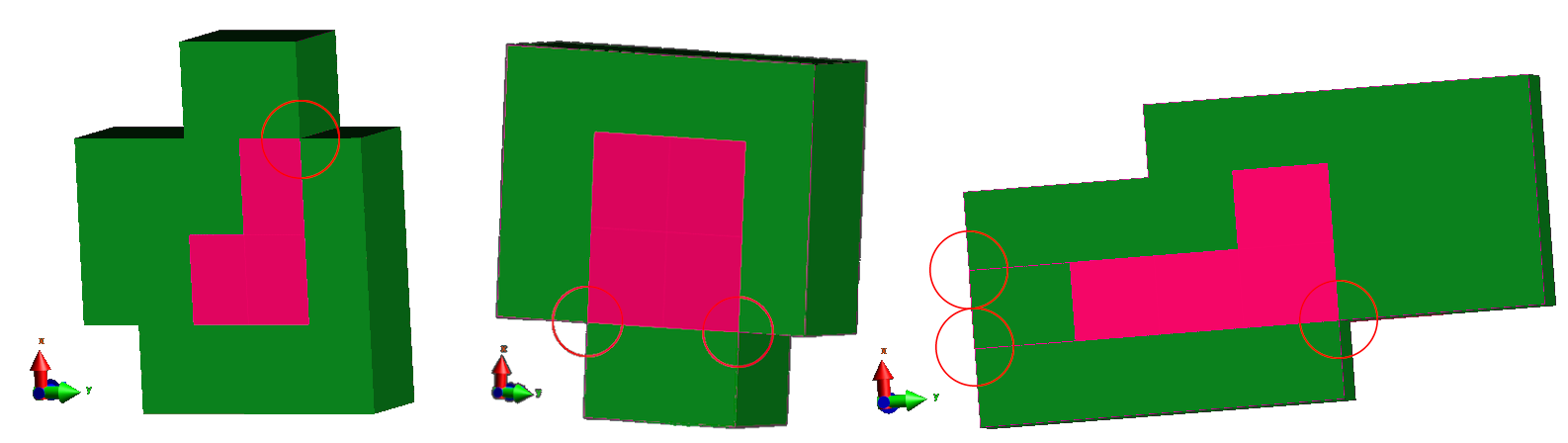
In Fig.2 we see how starting from a full CAD model, which renders to show exquisite detail, (Fig.2, Model), a final voxel model is produced and when visualised is clearly much coarser (Fig.2, Voxelization). Despite this the wire does seem to be fully encapsulated, yet the SAR simulation shows hotspots along the insulated part of the wire that are unexpected2 (Fig.2, SAR Errors).Upon closer analysis of the voxelization (Fig.3) it can be determined that there are points which allow for current leakage and consequently lead to errors. The problem locations occur where a vertex of a conductor voxel is at the surface of the insulator region, making a point contact with the medium outside the insulator layer (Fig 3, circled locations). These contact points are not readily seen at superficial inspection in a 3D view, and so are extremely difficult to trace.
Figure 4 illustrates the simplified simulation configuration, and Fig.5 plots the current distributions along the wire for the three scenarios. Despite the underlying geometry being the same, the induced current distributions vary substantially, and this appears to be entirely due to small details in the model at the voxel level.
Conclusion
Choice of voxelization is known to be critical for achieving accurate simulation results. Scenarios such as those investigated here present major challenges and appear to demand ever finer meshes, but these soon become unfeasible for real world computation. The presence of unanticipated hotspots on apparently completely insulated surfaces (as seen in Fig.2) and the very large differences in current distributions (such as seen in Fig.5) for ostensibly rather similar scenarios suggests that the underlying details can be critically important. Although hard to spot, these issues have a very substantial impact on the outcome of the simulations and so should not be disregarded. How best to resolve them, and how to report results when there are challenges, remains to be further investigated.Acknowledgements
JNT is funded by MRC CASE studentship [MR/P01674X/1]. This work was supported by the Wellcome EPSRC Centre for Medical Engineering at Kings College London [WT 203148/Z/16/Z], MRC strategic grant [MR/K006355/1], MRC development pathways funding scheme [MR/N027949/1], and by the National Institute for Health Research (NIHR) Biomedical Research Centre based at Guy’s and St Thomas’ NHS Foundation Trust and King’s College London. The views expressed are those of the authors and not necessarily those of the NHS, the NIHR or the Department of Health.References
1. R. Courant, K. Friedrichs, and H. Lewyt, “On the Partial Difference Equations of Mathematical Physics,” Math. Ann., vol. 138, no. 2, pp. 179–202, 1959.
2. J. A. Nyenhuis, S. M. Park, R. Kamondetdacha, A. Amjad, F. G. Shellock, and A. R. Rezai, “MRI and implanted medical devices: Basic interactions with an emphasis on heating,” IEEE Trans. Device Mater. Reliab., vol. 5, no. 3, pp. 467–479, 2005.
Figures