4250
Investigation of Various Self-Decoupled Body Coil Arrays at Ultrahigh Fields1Vanderbilt University Institute of Imaging Science, Nashville, TN, United States, 2Department of Radiology, Vanderbilt University Medical Center, Nashville, TN, United States, 3College of Nuclear Equipment and Nuclear Engineering, Yantai University, Yantai, China, 4Department of Biomedical Engineering, Vanderbilt University, Nashville, TN, United States
Synopsis
At ultrahigh fields, to achieve ultimate receive performance, the optimal current patterns go beyond the uniform current of loops. A dipole-like current is desired and can be realized by directly adding dipole antennas or by inducing dipole-mode in loops. In this work, we investigated the receive performance of different kinds of arrays with self-decoupled loops (SDLs) or/and self-decoupled folded dipoles (SDFDs). These coils have dipole-like as well as loop-like patterns and are highly isolated. We found that the combination of SDL and SDFD exhibits considerable improvement for both peripheral/central SNR and parallel imaging, even compared to mixed loop+dipole arrays.
Purpose
At ultrahigh fields, to achieve ultimate receive performance, the optimal current patterns go beyond the uniform current of loop arrays [1, 2]. A dipole-like current is desired and can be realized by directly adding dipole antennas [3,4] or by inducing dipole-modes in loops [5]. However, coupling between elements is a problem when building arrays of these elements. Although overlapping can cancel the magnetic coupling between loops, it is not applicable for dipole-like coils where electric coupling arises. In this work, we investigated the receive performance of different kinds of arrays with self-decoupled loops (SDLs) [6,7] and self-decoupled folded dipoles (SDFDs) [8]. These coils could have dipole-like current patterns as well as loop-like patterns, and all elements are highly isolated. We also compared their performance with previously reported loop-only, dipole-only and loop+dipole arrays.Methods
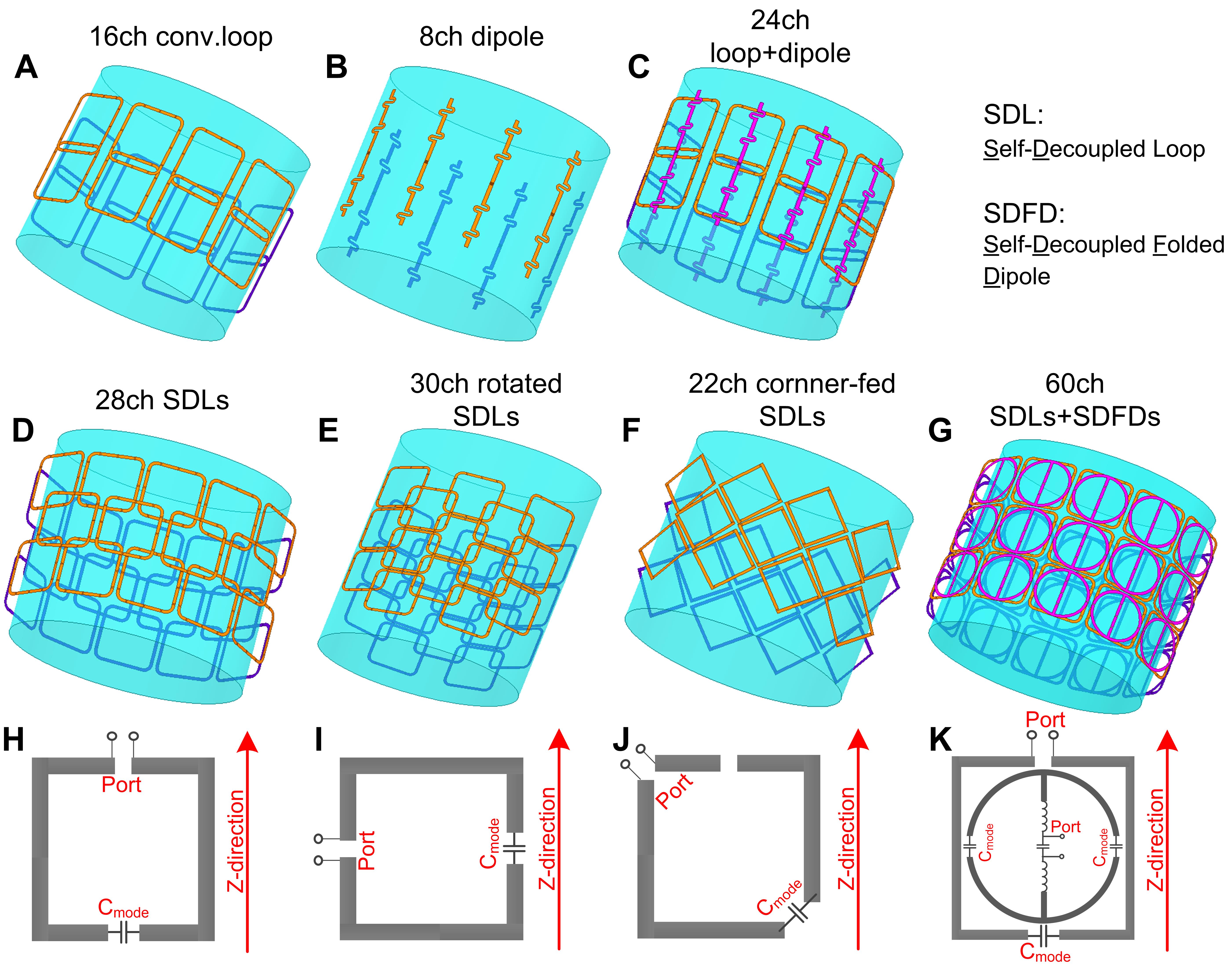
All simulations were performed with Ansys at 7T in body imaging configurations. Figures 1A-C show the simulation model of a conventional loop-only array, a segmented dipole array [9] and a combination of the two, which are used for baseline comparisons. Figures 1D-1G show simulation models of arrays with different types of SDLs or/and SDFDs. Figures H-K illustrate the diagram of each array. Note that for all configurations, the feed port has the strongest current while the Cmode has the weakest current.For the 28-ch SDL array (Figures 1D and H), each coil is fed on the top conductor, and Cmode is positioned on the bottom conductor. Since the B1 fields are determined by currents along the coil arms, its EM fields are expected to be similar to a conventional loop coil. Overlapping is applied to reduce the coupling between adjacent rows. For the 30-ch rotated SDL array (Figures 1E and I), each coil is fed on the left arm, and Cmode is positioned on the right arm. Since currents along the two arms are not balanced, its EM fields should be between a dipole and a loop (similar to a loopole, but with more unbalanced currents). Overlapping is applied to reduce the coupling between adjacent columns. For the 22-ch rotated corner-fed SDL array (Figures 1F and J), its current pattern and EM fields are similar to those of rotated SDL array, but with no need to be overlapped. For the 60-ch SDL+SDFD array (Figures 1G and K), each SDL is the same as the SDL in Figure 1D, while SDFD has a figure-of-8 shape and a similar current distribution as a straight dipole [6].
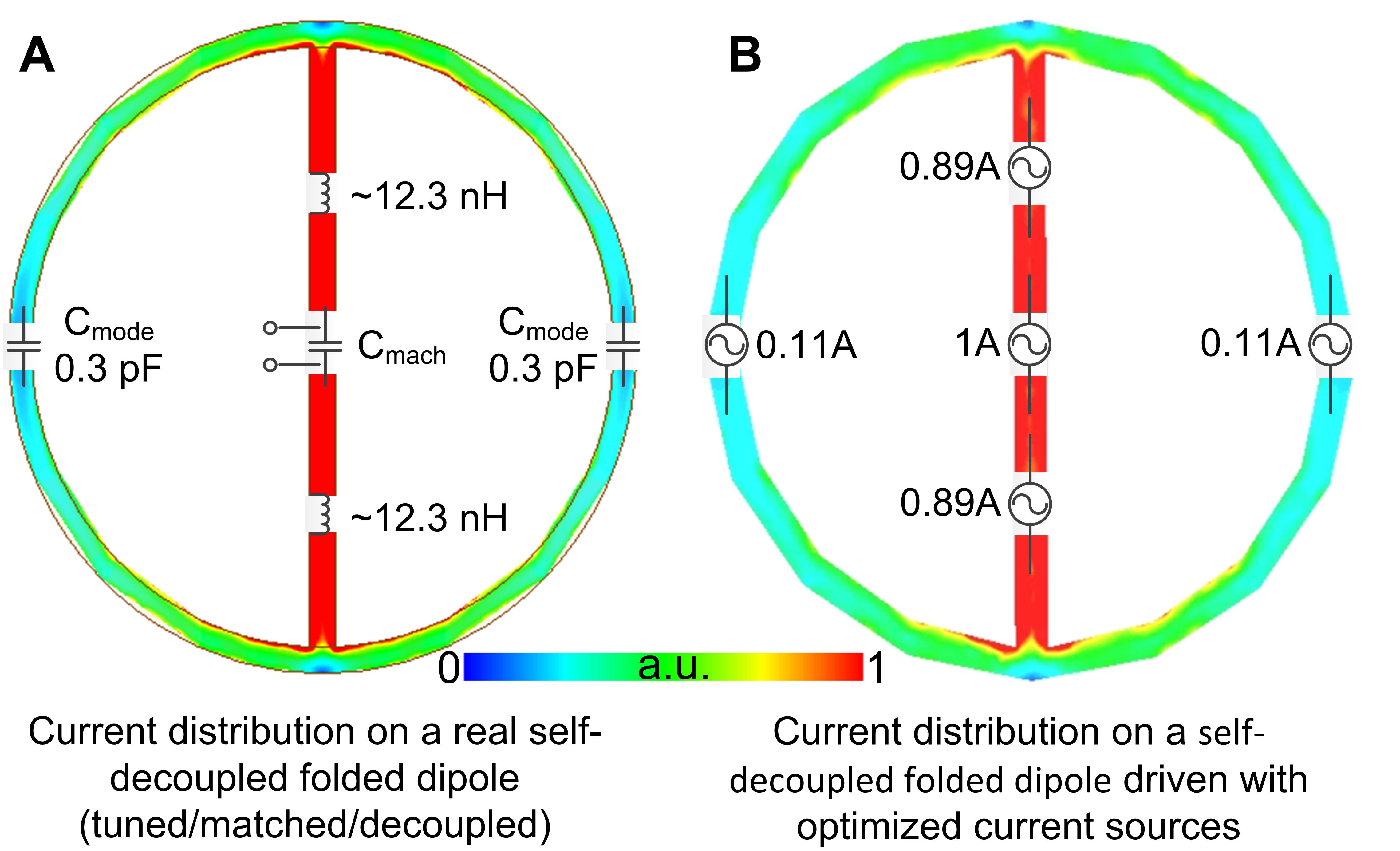
A current source driven simulation method was applied to calculate the arrays’ EM fields, SNR and g-factor, the accuracy and reliability of which has been validated [10-12]. The conventional loop coil was driven by 12 unit current sources. For the SDL and SDFD coils, the current sources were optimized using the fmincon function in Matlab to match the current distribution in a real coil where tuning/matching/decoupling are considered. Figure 2 shows one example of the SDFD coil. It can be clearly seen that the current distribution driven with optimized current sources (Figure 2B) is almost the same as that of a real coil (Figure 2A).
Results and Discussions
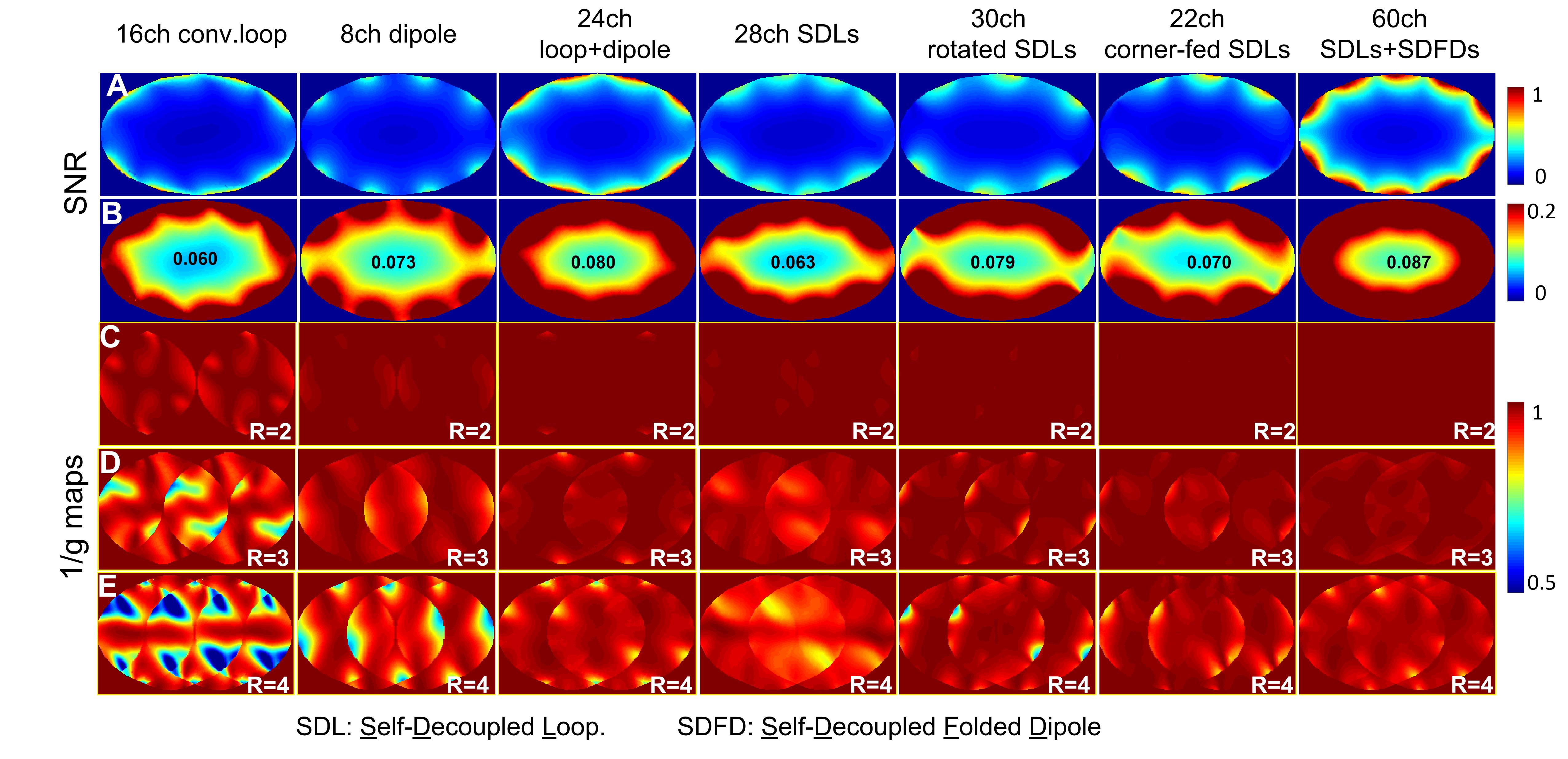
Figures 3a and 3b show the SNR maps in a central axial slice, with the central SNR marked. Similar to previous work [3, 4], the combination of dipole and loop coil (3rd column) can increase the SNR at both the peripheral area and the central area compared to loop-only (1st column) and dipole-only (2nd column) arrays. In particular, the dipole+loop array has a central SNR improvement of 33% (0.08 vs. 0.06) compared to a loop-only array.As expected, the 28-ch SDL array has almost the same EM fields and thus the same SNR as the loop-only array. When the SDL is rotated by 90 degrees, it acts as a loopole [5] and exhibits almost the same central SNR as the loop+dipole array (0.079 vs. 0.080) but with a lower peripheral SNR. Note that the rotated SDL's B1+ and B1- fields behave differently. In this work, it was fed on one left arm to maximize the B1-, and thus B1+ transmit efficiency was sacrificed. Although the corner-fed SDL array is easier to fabricate without requiring overlapping, it does not show any peripheral or central SNR benefits compared to the loop+dipole array.
The 60ch SDL+SDFD shows the best peripheral SNR and best central SNR among all these coils. Even compared with a dipole+loop array, it exhibits 11% central SNR improvement. Due to its folded design, it accommodates more coils and thus exhibits much lower g-factor (Figures C-E).
Conclusion
We investigated the receive performance of different kinds of body coil arrays using self-decoupled loops (SDL) and self-decoupled folded dipoles (SDFD), and compared them with a previously reported loop-only array, a dipole-only array and loop+dipole arrays. We found that SDL arrays do not have any SNR improvement compared to loop+dipole array, even when the coils are rotated 90 degree to behaves like a loopole. However, we found that the combination of SDL and SDFD exhibits considerable improvement for both peripheral/central SNR and parallel imaging.Acknowledgements
This work was partially supported by NIH Grant R01 EB 016695.References
1. Lattanzi, R., Wiggins, G. C., Zhang, B., Duan, Q., Brown, R., & Sodickson, D. K. (2018). Approaching ultimate intrinsic signal‐to‐noise ratio with loop and dipole antennas. Magnetic resonance in medicine, 79(3), 1789-1803.
2. Pfrommer, A., & Henning, A. (2018). The ultimate intrinsic signal‐to‐noise ratio of loop‐and dipole‐like current patterns in a realistic human head model. Magnetic resonance in medicine, 80(5), 2122-2138.
3. Ertürk, M. A., Raaijmakers, A. J., Adriany, G., Uğurbil, K., & Metzger, G. J. (2017). A 16‐channel combined loop‐dipole transceiver array for 7 T esla body MRI. Magnetic resonance in medicine, 77(2), 884-894.
4. Steensma, B. R., Voogt, I. J., Leiner, T., Luijten, P. R., Habets, J., Klomp, D. W., ... & Raaijmakers, A. J. (2018). An 8-channel Tx/Rx dipole array combined with 16 Rx loops for high-resolution functional cardiac imaging at 7 T. Magnetic Resonance Materials in Physics, Biology and Medicine, 31(1), 7-18.
5. Lakshmanan, K., Cloos, M. A., Lattanzi, R., Sodickson, D. K. & Wiggins, G. C. in International Society for Magnetic Resonance in Medicine 397 (Milan, 2014).
6. Yan, X., Gore, J. C., & Grissom, W. A. (2018). Self-decoupled radiofrequency coils for magnetic resonance imaging. Nature communications, 9(1), 3481.
7. Yan, X., Gore, J. C., & Grissom, W. A. (2018). Multi-row and Loopole-type Self-decoupled RF Coils, ISMRM, 4271.
8. Self-decoupled Folded Dipole Antenna, submitted to ISMRM 2020.
9. Raaijmakers, A. J., Italiaander, M., Voogt, I. J., Luijten, P. R., Hoogduin, J. M., Klomp, D. W., & van Den Berg, C. A. (2016). The fractionated dipole antenna: A new antenna for body imaging at 7 T esla. Magnetic resonance in medicine, 75(3), 1366-1374.
10. Yang QX, Wang J, Wang J, Collins CM, Wang C, Smith MB. Reducing SAR and enhancing cerebral signal-to-noise ratio with high permittivity padding at 3 T. Magn Reson Med, 2011;65:358-362.
11. Luo, W., Lanagan, M. T., Sica, C. T., Ryu, Y., Oh, S., Ketterman, M., ... & Collins, C. M. (2013). Permittivity and performance of dielectric pads with sintered ceramic beads in MRI: early experiments and simulations at 3 T. Magnetic resonance in medicine, 70(1), 269-275.
12. Liu, F., Beck, B. L., Fitzsimmons, J. R., Blackband, S. J., & Crozier, S. (2005). A theoretical comparison of two optimization methods for radiofrequency drive schemes in high frequency MRI resonators. Physics in Medicine & Biology, 50(22), 5281.
13. Pruessmann, K. P., Weiger, M., Scheidegger, M. B., & Boesiger, P. (1999). SENSE: sensitivity encoding for fast MRI. Magnetic resonance in medicine, 42(5), 952-962.
Figures