4248
A Coil-Winding Machine for Wet-Winding of Resin-Impregnated Curved Wire Patterns1Department of Biomedical Engineering, Columbia University, New York, NY, United States, 2Hamburg University of Technology, Hamburg, Germany, 3Department of Radiology, Columbia University, New York, NY, United States
Synopsis
The development of advanced Multi-Coil (MC) setups for the generation of MRI encoding fields necessitates the manufacture of wire wound coil fixated with epoxy resin. Common winding techniques, however, are not suitable for the required geometries. As a remedy, we developed an automated coil winding machine capable of winding coils with a large number of turns in irregular curved shapes whilst impregnating them with epoxy resin.
Introduction
Magnetic fields needed for image encoding and B0 shimming in magnetic resonance imaging (MRI) are traditionally generated by dedicated coils targeting low-order specific spherical harmonic shapes. It has recently been shown that the multi-coil (MC) technique utilizing an array of smaller individually driven coils can be a versatile tool to generate complex target fields in a flexible fashion. This approach has been successfully used both statically and dynamically for B0 shimming in rodents1,2 and humans3,4, and has been demonstrated to be capable of generating image encoding fields in both miniaturized and human-size setups5–7.Traditional gradient coils are optimized for fast switching and, therefore, consist of a minimum number of conductor turns driven with high currents to minimize inductance. So far, most MC prototypes focused on B0 shimming with low current amplifiers (1 A max.) and were accordingly built as simple hand-wound coils of a hundred turns or less mounted to an acrylic former. For a novel head-only MR scanner we are currently building a more advanced MC setup8 capable of generating linear gradients with a strength of up to 10 kHz/cm across the human head that, while still designed as a low current system (5 A max.), necessitates the incorporation of water cooling and the use of more sophisticated engineering approaches (Figure 1). In this setup, individual MC coil elements consist of two 100-turn elements (i.e. 200 turns total) that are sandwiched together with an integrated piping structure for water cooling. A wet-winding technique is used to immerse the wires in ceramic-filled epoxy resin for increased thermal conductivity and to avoid mechanical vibration under strong B0-induced Lorentz forces. Numerous methods (e.g. fly winding or needle winding9) commonly used for flat coils in motor industry, however, are not suitable for wet-winding of required curved coil geometries (cf. Figure 2A) . In addition, the manual construction of 62 coil elements for the 31 composite coils of the MC array at hand (Figure 1) would be both labor-intensive and error-prone. Here we present a novel molding method for the construction of resin-impregnated wire patterns with irregular curved shapes along with a microcontroller-driven motorized machine for automated coil construction.
Design
An aluminum mold was designed in SolidWorks (Dassault Systèmes, Vélizy-Villacoublay, France) and machined by CNC milling to act as a bobbin and define the shape of the coil to be produced (Figure 2B). The mold is fixated on a rotary table (Figure 3A). A swinging arm rotates up and down to guide the vertical position of the wire synchronized with the rotation of the mold, ensuring accurate winding and preventing scratching of the wire on the edges. The effective length of the arm has been designed adjustable to be able to adapt to different mold sizes. Both the rotary table and the swinging arm are driven by stepper motors that are controlled by a single microcontroller (Arduino Due) via individual step drivers (G203V, Geckodrive Inc., Santa Ana, CA, USA). An epoxy resin feed tank was added to the swinging arm to automatically dispense epoxy resin to the wire. A photograph of the system realization is shown in Figure 3B.The microcontroller was programmed so that the mold is rotating at a constant speed. The optimal angle of the arm as a function of table position was measured (Figure 4) and converted to text files specifying the necessary motor steps using a python script and read by the microcontroller from an SD card at the start of the winding process. The optimal angle of the arm depends on the number of turns already wound onto the mold and the synchronization has to be updated throughout the winding process of the coil to account for it.
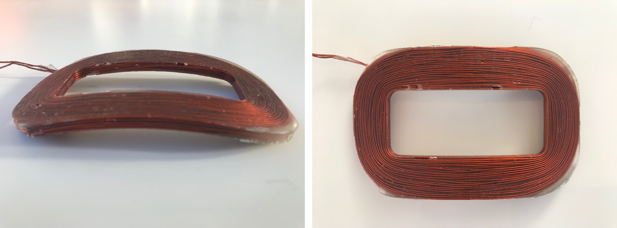
To prevent loose wire loops and maximize the wire density in the mold volume, a wire tensioner (TCL2, ACME Mechatrons Inc., TX, USA) was used to ensure constant wire tension throughout the entire winding process. For the project at hand AWG 20 (diameter 0.9 mm) insulated copper wire with a constant tension of 40 N was used. An example curved coil element (length 115 mm, height 73 mm, width 4 mm, radius 16 cm) with 100 turns of copper wire is shown in Figure 5.
Discussion & Outlook
A coil winding machine has been presented for automated wet-winding of curved copper coil elements for advanced MC applications. Tension control ensures tight wire packing, however, wire crossing cannot be fully avoided which yields a fill factor of 68% and the optimal fill factor of orthocyclic winding is not achieved (90.7%). Synchronization of the swinging arm and the rotary table in this prototype is based on manual measurements of arm and angle positions, respectively. Future extensions include the calculation of optimum angles directly from the established CAD model of the device, thereby simplifying the adaptation to specific coil geometries. In addition, a feedback mechanism of the motor control will be included for refined synchronization accuracy of the stepper motors throughout the winding process. A comprehensive configuration of the employed microcontrollers driving the two motors based on real-time position measurements is furthermore expected to enable elevated winding speed and increased productivity.Acknowledgements
This research was supported by the National Institute of Biomedical Imaging and Bioengineering of the National Institutes of Health under award number U01EB025153.References
1. Juchem, C. et al. Multicoil shimming of the mouse brain. Magn. Reson. Med. 66, 893–900 (2011).
2. Juchem, C. et al. DYNAmic Multi-coIl TEchnique (DYNAMITE) shimming of the rat brain at 11.7T. NMR Biomed. 27, 897–906 (2014).
3. Stockmann, J. P. et al. A 32-channel combined RF and B0 shim array for 3T brain imaging. Magn. Reson. Med. 75, 441–451 (2016).
4. Juchem, C. et al. Dynamic multi-coil shimming of the human brain at 7 T. J. Magn. Reson. 212, 280–288 (2011).
5. Juchem, C., Nixon, T. W., McIntyre, S., Rothman, D. L. & de Graaf, R. A. Magnetic field modeling with a set of individual localized coils. J. Magn. Reson. 204, 281–289 (2010).
6. Juchem, C., Nahhass, O. M., Nixon, T. W. & de Graaf, R. A. Multi-slice MRI with the dynamic multi-coil technique. NMR Biomed. 28, 1526–1534 (2015).
7. Juchem, C. et al. Dynamic Multi-Coil Technique (DYNAMITE) MRI on Human Brain. in Proceedings of the International Society for Magnetic Resonance in Medicine 27, 0219 (2019).
8. Theilenberg, S., Shang, Y., Kobayashi, N., Parkinson, B. J. & Juchem, C. Multi-Coil Array for Combined Imaging and B0 Shimming in a Portable Head-Only Scanner. in Proceedings of the International Society for Magnetic Resonance in Medicine 27, 1480 (2019).
9. Handbook of Coil Winding. (Springer, 2018). doi:10.1007/978-3-662-54402-0
Figures