4247
The X-Mode Gradient: Improved Performance for Select Applications1Department of Medical Biophysics, Western University, London, ON, Canada, 2Department of Physics, Western University, London, ON, Canada
Synopsis
In this work a design study of a shoulder cut-out gradient coil for use in a head-only MRI platform was performed. Specifically, based on previous work, it explored the effect of rotating the gradient axes on performance. This was due to the imbalance of gradient performance degradation due to the presence of cut-outs on conducting surfaces next to the patient's shoulders. This proof-of-concept exploration is the first demonstration of the feasibility of rotating the gradient axes during the design process to design a shoulder cut-out gradient coil.
Introduction
Previously, we have proposed the development and use of an actively shielded gradient coil with cut-outs to accommodate the patients shoulder for use in a head-only MRI system, allowing imaging below the brain and into the cervical spine.1 This setup would allow imaging of both the brain and cervical spine regions with only limited patient translational movement. Unfortunately, the presence of cut-outs in the conducting surfaces next to the patient’s shoulders leads to an imbalance in the performance between gradient axes, specifically, the X-gradient has a larger degradation in performance compared to a full cylinder than is observed for the Y-gradient. Therefore, in this work we propose a novel gradient configuration where the transverse axes are each rotated by $$$\frac{\pi}{4}$$$ which preserves orthogonality but may serve to better balance the gradient performance. Therefore, in this proof-of-concept study we performed electromagnetic design simulations to explore the effect of rotated gradient axes. We hypothesize that by rotating the transverse axes by $$$\frac{\pi}{4}$$$ we will have an improvement in the previously X-gradient performance and a decrease in the previously Y-gradient performance allowing a better-balanced gradient coil configuration.Methods
Triangular element meshes were created using COMSOL Multiphysics (COMSOL, Burlington, MA) and composed of a primary surface (length = 0.76 m, radius = ~0.22 m), a shield surface (length = 1.00 m, radius = 0.26 m) and a bore surface (length = 1.00 m, radius = 0.325 m). The cut-out size was held constant with a height (Y-direction) of 0.15 m and a length (Z-direction) of 0.21 m. The boundary element method (BEM)2-4 was implemented using custom built MATLAB (Mathworks, Natick, MA) software aiming for control of field uniformity and minimum wire spacing2 by performing a grid search of weighting parameters as previously described.1 To employ the BEM a set of discrete field targets were chosen as a 0.20 m diameter sphere situated at the isocentre. The field targets were a linear field gradient rotated by $$$\frac{\pi}{4}$$$. We denote the rotated reference frame directions as d1 and d2. Figure 1 shows a sample computational mesh and illustration of gradient directions. For our design algorithm we set the target efficiency to 0.125 mT/m/A while the minimum wire spacing for the gradients were chosen as 3.5 mm to accommodate realistic manufacturing capabilities. However, due to the efficiency target not all solutions will converge to an appropriate minimum wire spacing and those with a minimum spacing of < 3.5 mm were discarded and not considered for later analysis.Results
Examples of the transverse gradients are shown in Figure 2 and their respective electromagnetic properties are given in Table 1. Contour plots of percent deviation from the center field value are shown in Figure 2, the maximum diameter of a sphere within the 30% line is given as DSV30 in Table 1. Simulated magnetic field maps, normalized per unit current, are shown in Figure 3.Discussion
Previous work has demonstrated the difficulty in designing a gradient coil with shoulder cut-outs where both gradient axes have similar performance. This is due to limiting allowed regions for current to flow on the sides of the patient’s shoulders. As shown in Table 1 the rotation of the gradient axes allows the X- and Y-gradients to obtain similar performance to each-other while achieving electromagnetic properties acceptable for imaging. There is high homogeneity as evidenced in Figure 1 and a large imaging region defined by the DSV30 of approximately 0.28 m for each axis. The designs presented are well shielded with low power deposited into the computational bore surface. Interestingly, although well balanced there is a difference in the minimum wire separation between the two presented wire gradients. This will result in slightly higher localized heating in the d1-gradient however, both axes are machinable given current manufacturing capabilities. Also, as evidenced in Figure 1 there is a loss of symmetry within the homogeneity plots. One important future direction is to move the imaging region further towards the patient end allowing direct comparison of previous work and the potential to improve cervical spine imaging while still allowing imaging of the brain.Conclusion
We have performed a preliminary design study to explore the effect of rotating the gradient axes on performance in an actively shielded shoulder cut-out gradient coil. This proof-of-concept study demonstrates the feasibility of designing a gradient coil with shoulder cut-outs that well balances the performance of the transverse axes. To date this is the first theoretical demonstration of the feasibility of rotating the gradient axes to design a shoulder cut-out gradient coil.Acknowledgements
The authors acknowledge financial support from NSERC and the Ontario Research Fund.References
1. Lessard EJ et al. Proc. Intl. Soc. Mag. Reason. Med. 27 (2019) Abstract #1481
2. Harris CT et al. Concepts Magn. Reson., 41B: 120-129 (2012)
3. Poole M, and Bowtell R., Concepts Magn. Reason., 31B(3): 162-175 (2007)
4. Harris CT et al. J. Magn. Reson. Imaging., 234: 95-100 (2013)
Figures
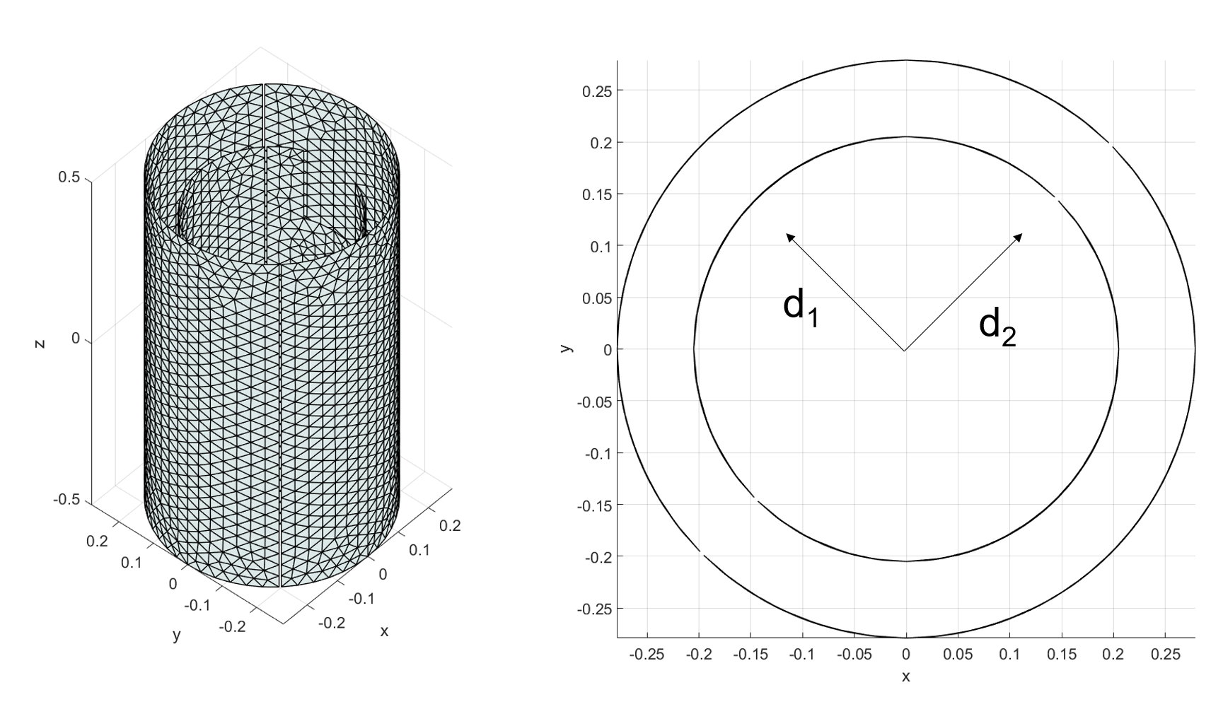
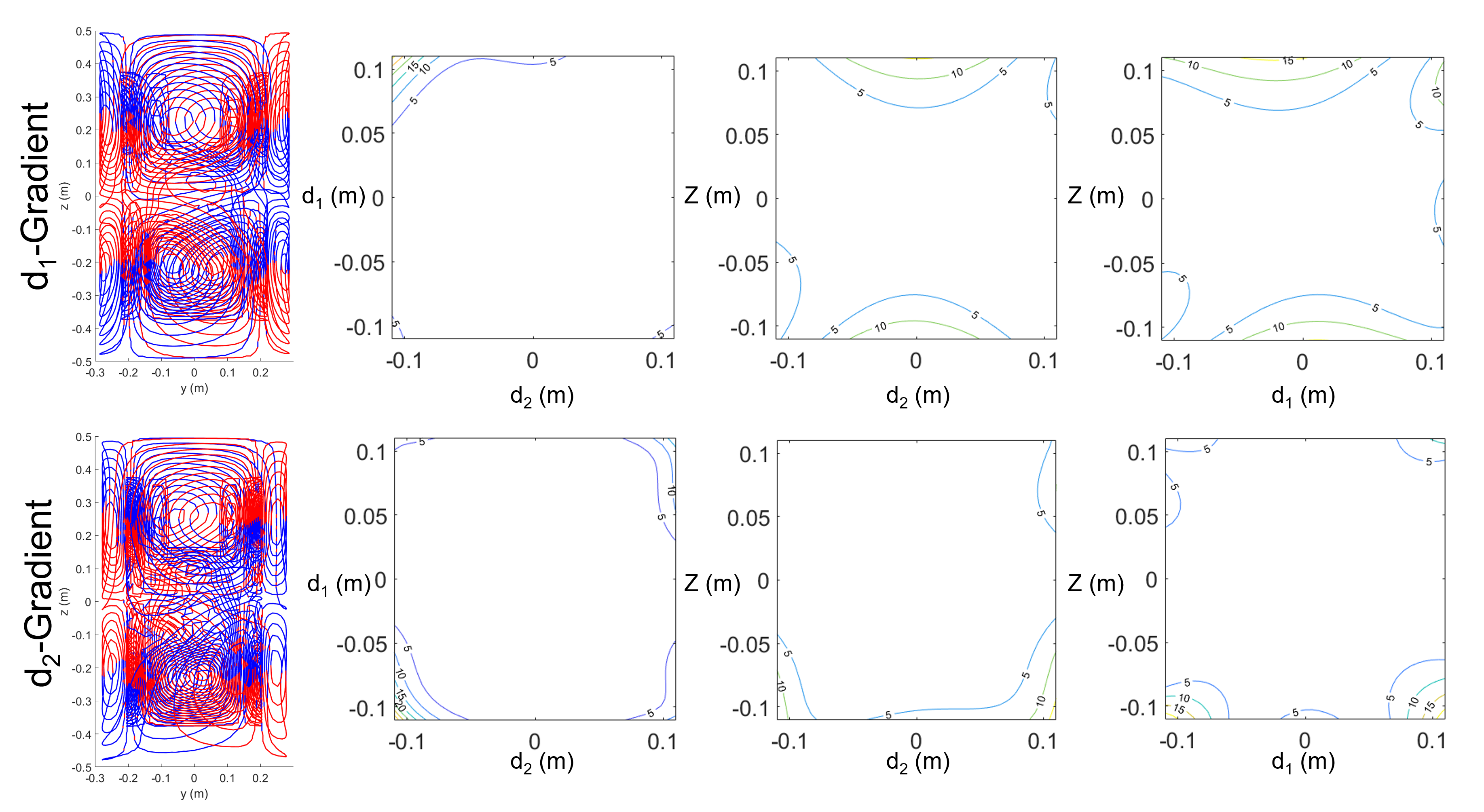
Figure 2: Example wire patterns and homogeneity plots for "X-Mode" d1- and d2-gradient shoulder cut-outs.
Colour indicates current direction with respect to azimuthal direction.
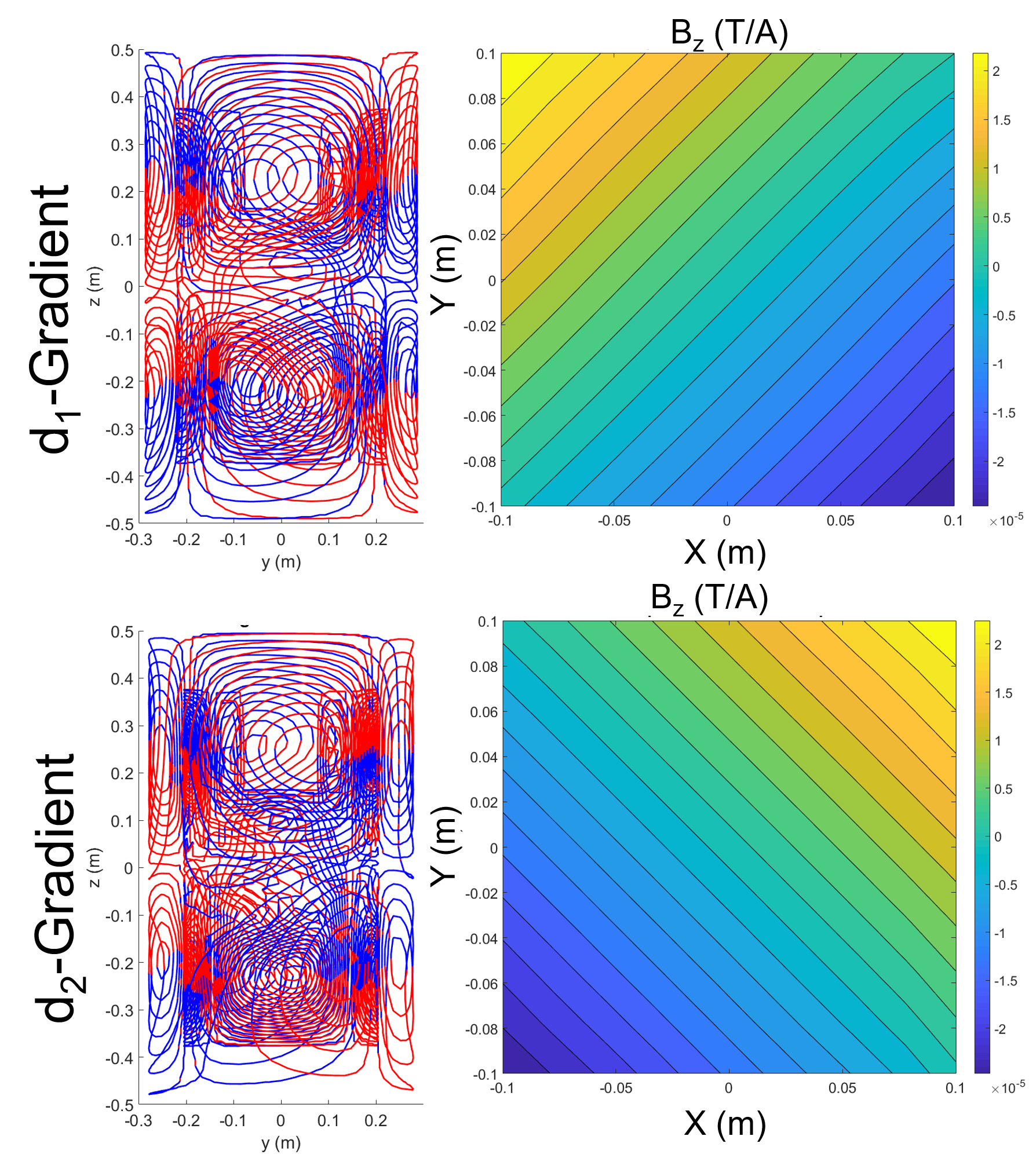
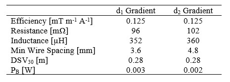
Table 1: Theoretical Electromagnetic and Electrical Properties of Shoulder Cut-out d1- and d2-Gradient coils.
DSV30 = diameter of a spherical volume in which the gradient field deviates no more than 30%
PB = power deposited in the bore surface when driven with 1 A of current through gradient coil