4246
Design of a high-performance human-breast non-linear gradient coil for diffusion weighting
Feng Jia1, Sebastian Littin1, Philipp Amrein1, Huijun Yu1, Arthur Magill2, Tristan Kuder2, Sebastian Bickelhaupt3, Frederik Laun4, Mark E. Ladd2, and Maxim Zaitsev1
1Dept.of Radiology, Medical Physics, Medical Center University of Freiburg, Faculty of Medicine, University of Freiburg, Freiburg, Germany, 2Medical Physics in Radiology, German Cancer Research Center, Heidelberg, Germany, 3Junior Group Medical Imaging and Radiology – Cancer Prevention, German Cancer Research Center (DKFZ), Heidelberg, Germany, 4Department of Radiology, MR Physics, University Medical Center Erlangen, Erlangen, Germany
1Dept.of Radiology, Medical Physics, Medical Center University of Freiburg, Faculty of Medicine, University of Freiburg, Freiburg, Germany, 2Medical Physics in Radiology, German Cancer Research Center, Heidelberg, Germany, 3Junior Group Medical Imaging and Radiology – Cancer Prevention, German Cancer Research Center (DKFZ), Heidelberg, Germany, 4Department of Radiology, MR Physics, University Medical Center Erlangen, Erlangen, Germany
Synopsis
A nonlinear human-breast coil for diffusion weighting with a high performance 1T/m is designed.
Introduction
Recently, the concept of a “high power diffusion probe”1 with a required gradient strength of over 1T/m and high slew rate has been proposed for diffusion weighting in human breast MRI. In order to meet the requirement, a non-linear gradient coil design methodology2 has been proposed to develop a unilateral single-channel breast gradient coil3. That gradient coil3 was shown to generate an encoding field of a higher gradient strength in a region of interest (ROI) than its linear counterpart. However, it was recognized that the strong non-linearity of the generated encoding field may pose a challenge to a data acquisition and image reconstruction for diffusion-weighted imaging (DWI). Moreover, the mentioned coil design has an asymmetric wire pattern which can generate an unbalanced torque. In this work, an optimization problem is formulated to control the distribution of a resulting encoding field over the ROI in order to handle the challenge to the DWI acquisition in future. Torque-balance constraints are also considered in the optimization.Methods
Unlike the previous breast coil3, an encoding field generated by a new breast coil is required to have a nearly constant absolute value of the gradient strength in every coronal slices and a non-linearity only along y-axis. This requirement will allow one to use the new coil for DWI in coronal orientaton without any modification of the established imaging protocols. Besides this requirement, coil power dissipation is minimized and the gradients of the generated field within an ROI need to be controlled. Moreover, wire track widths and torque balance were controlled for the practical fabrication and safe operation of the coil, respectively.Based on the requirements above, an optimization problem for a non-linear coil is proposed as follows:
$$\min_{\psi}\mbox{ }F,\mbox{ }F:=\sqrt{P(\psi)}+ \alpha_J \lVert\vec{J}(\psi)\rVert_{p},\\\mbox{subject to } \mbox{ }\frac{1}{k}\sum_{\vec{x}_i\in{\text{ROI}}}\left|\nabla B_z(\psi,\vec{x}_i)\right|\geq C_g,\nonumber \\\mbox{ }\frac{1}{k\sqrt{P(\psi)}}\left( \sum_{\vec{x}_i\in{\text{ROI}}}\left(\frac{\left|\nabla B_z(\psi,\vec{x}_i)\right|}{\partial x}\right)^2+\left(\frac{\left|\nabla B_z(\psi,\vec{x}_i)\right|}{\partial z}\right)^2 \right)^\frac{1}{2}\leq C_c,\\\mbox{ }|M_x|:=\left|\int_{\Gamma}B_0J_x(\psi)zd\Gamma\right|\leq M_{\max},\nonumber\\\mbox{ }|M_y|:=\left|\int_{\Gamma}B_0J_y(\psi)zd\Gamma\right|\leq M_{\max},\nonumber\\\mbox{ }|M_z|:=\left|-\int_{\Gamma}B_0\left(J_x(\psi)x+J_y(\psi)y\right)d\Gamma\right|\leq M_{\max},\nonumber$$
where $$$\psi$$$ denotes the scalar piecewise-linear stream function4 of the electric current density vector $$$\vec{J}(\psi):=(J_x(\psi),J_y(\psi),J_z(\psi))^T$$$ and $$$\vec{J}(\psi) = \nabla\times(\psi\vec{n})$$$ on a current-carrying surface $$$\Gamma$$$ (Fig. 1) with a normal unit vector $$$\vec{n}$$$. $$$\tau$$$ indicates the thickness of the surface $$$\Gamma$$$, $$$\sigma$$$ is the electrical conductivity of the surface $$$\Gamma$$$. The $$$B_z$$$ is z-components of the magnetic field $$$\vec{B}$$$ generated by current densities $$$\vec{J}$$$ on $$$\Gamma$$$, which is calculated using the Biot-Savart law. The points $$$\vec{x}_i = (x_i, y_i, z_i)^T$$$, $$$i=1,\ldots, k$$$, denote the coordinate vectors of $$$k$$$ test points in the ROI. One positive constant $$$\alpha_J$$$ is tuned to achieve an enough width of wire tracks of the designed coil. $$$C_g$$$ and $$$C_c$$$ are used to control the gradient strength of the resulting encoding field and inhomogeneity of the gradient amplitude within coronal slices, respectively.
A linear $$$G_z$$$ gradient coil is first designed based on the approach of Jia et al.2 and then the resulting stream function is used as an initial value for the proposed optimizaiton problem. Simlutanously, $$$C_g$$$ and $$$C_c$$$ are calculated by using the encoding field obtained from the linear coil design. All numerical examples were solved with the function fmincon in MATLAB (The MathWorks. Natick, USA).
In order to assess different coil designes, three performance metrics are defined as follows:
$$\beta_P:=\frac{\sum_{\vec{x}_i\in{\text{ROI}}}\lvert\nabla B_z(\psi,\vec{x}_i)\rvert}{k\sqrt{P(\psi)}},\\\beta_W:=\frac{\sum_{\vec{x}_i\in{\text{ROI}}}\lvert\nabla B_z(\psi,\vec{x}_i)\rvert}{k\sqrt{W_m}},\\\nu_P:=\frac{1}{k\sqrt{P(\psi)}}\left( \sum_{\vec{x}_i\in{\text{ROI}}}\left(\frac{\left|\nabla B_z(\psi,\vec{x}_i)\right|}{\partial x}\right)^2+\left(\frac{\left|\nabla B_z(\psi,\vec{x}_i)\right|}{\partial z}\right)^2 \right)^\frac{1}{2}.$$
Here,$$$W_m$$$ denotes the magnetic energy3. Accorrding to the definations above, $$$\beta_P$$$, and $$$\beta_W$$$ indicate a resistive and inductive figure of merit. $$$\nu_P$$$ is used to assess average variation of the gradient strength of $$$B_z$$$ within coronal slices.
Results and discussion
Figure 2 presents performance comparison between the designed linear and non-linear gradient coils. As seen, the non-linear coil outperformed the linear one in several ways. Compared with the linear coil, the resistive figure of merit $$$\beta_P$$$ raises 1.96 times while $$$\nu_P$$$ remains the same for the non-linear coil. This increase is due to the reduction of dissipated power since the sum of gradient strength of the resulting $$$B_z$$$ does not vary for two coils. Moreover, the inductive figure of merit $$$\beta_W$$$ for the non-linear coil increases 1.78-fold although $$$\beta_W$$$ is not directly optimized in the proposed design method. Finally, the non-linear coil had a 2.72 times as high maximum coil efficiency $$$\eta$$$ (gradient strength per current) as the linear coil.Figure 3 shows a comparison of $$$\eta$$$ over the ROI. Although $$$\eta$$$ for the non-linear coil has a higher standard deviation than the linear coil, $$$\eta$$$ on each coronal slices tends to remain constant. For example, as seen in Figure 4, $$$\eta$$$ in the slice at y=-94.3mm for the non-linear coil has a similar distribution as the linear coil. However, the mean of $$$\eta$$$ in this slice for the non-linear case increases 3.78-fold as compared to the linear coil. Moreover, the currrent of only 167A flowing through the non-linear coil can achieve the gradient strength of 1T/m in the slice. Figure 5 depicts the resulting coil layouts.
Conclusion
A novel design method has been demontrated to obtain a breast gradient coil with the gradient strength of above 1T/m.Acknowledgements
This work was supported by the German Research Foundation (DFG) (Grant Number ZA 422/5-1).References
1. Palm T, Martin J, et al. Impact of slew rates on the performance of a novel high-gradient breast diffusion probe, ISMRM 2018 Paris p1622.
2. Jia F, Littin S, et al., Design of a shielded coil element of a matrix gradient coil, J Magn Reson. 2017;281:217-228.
3. Jia F, Littin S, et al. Design of breast gradient coil with the control of field nonlinearity, ISMRM 2018 Paris p1757.
4. Peeren GN, Stream function approach for determining optimal surface currents, J Comput Phys. 2003;191(1):305‐321.
Figures
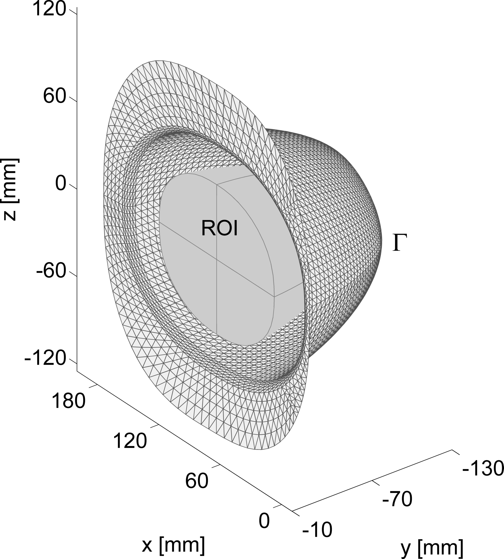
Fig. 1. Current-carrying surface ($$$\Gamma$$$) and the region of interest (ROI)
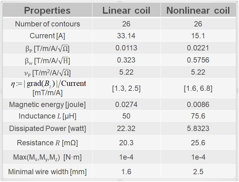
Fig. 2. Properties of the designed linear and nonlinear coils. Coil efficiency $$$\eta$$$ is defined as the ratio of gradeint strength of $$$B_z$$$ to the current flowing through the coils.
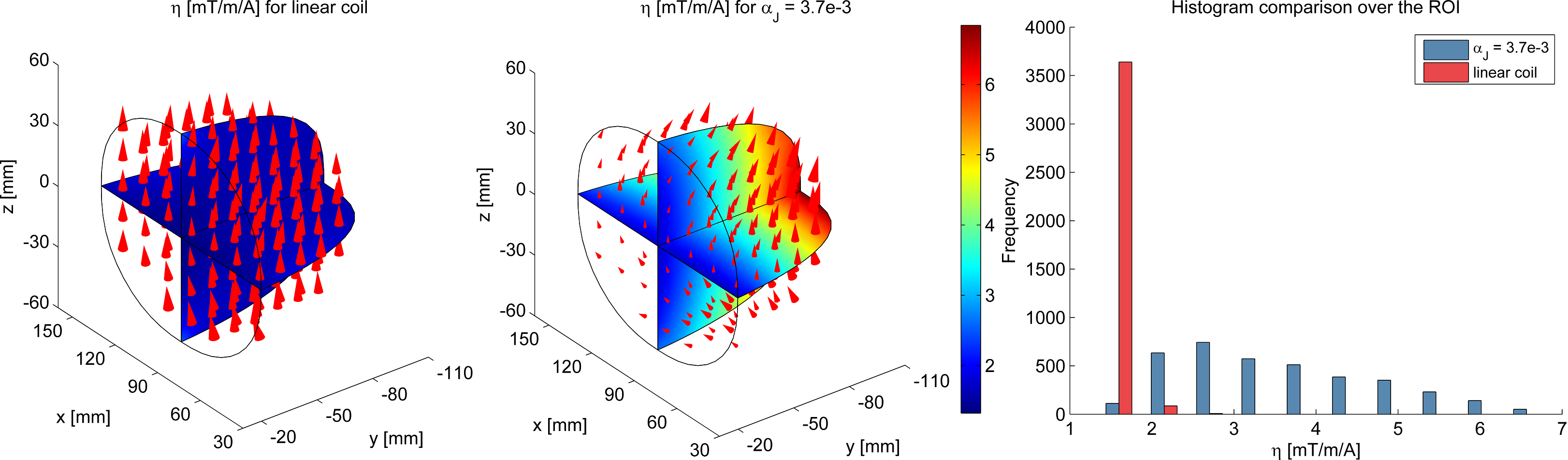
Fig. 3. Comparison of coil efficiencies $$$\eta$$$ over the ROI between the linear and nonlinear coils.
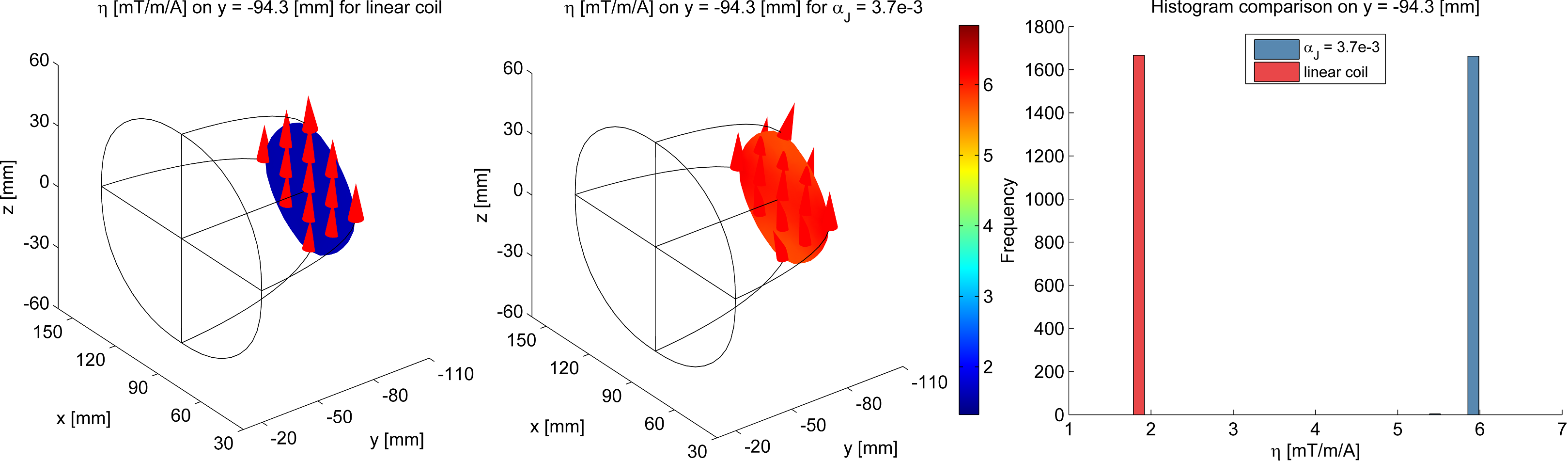
Fig. 4. Comparison of coil efficiencies $$$\eta$$$ between the linear and nonlinear coils in one selected slice at y=-94.3mm.
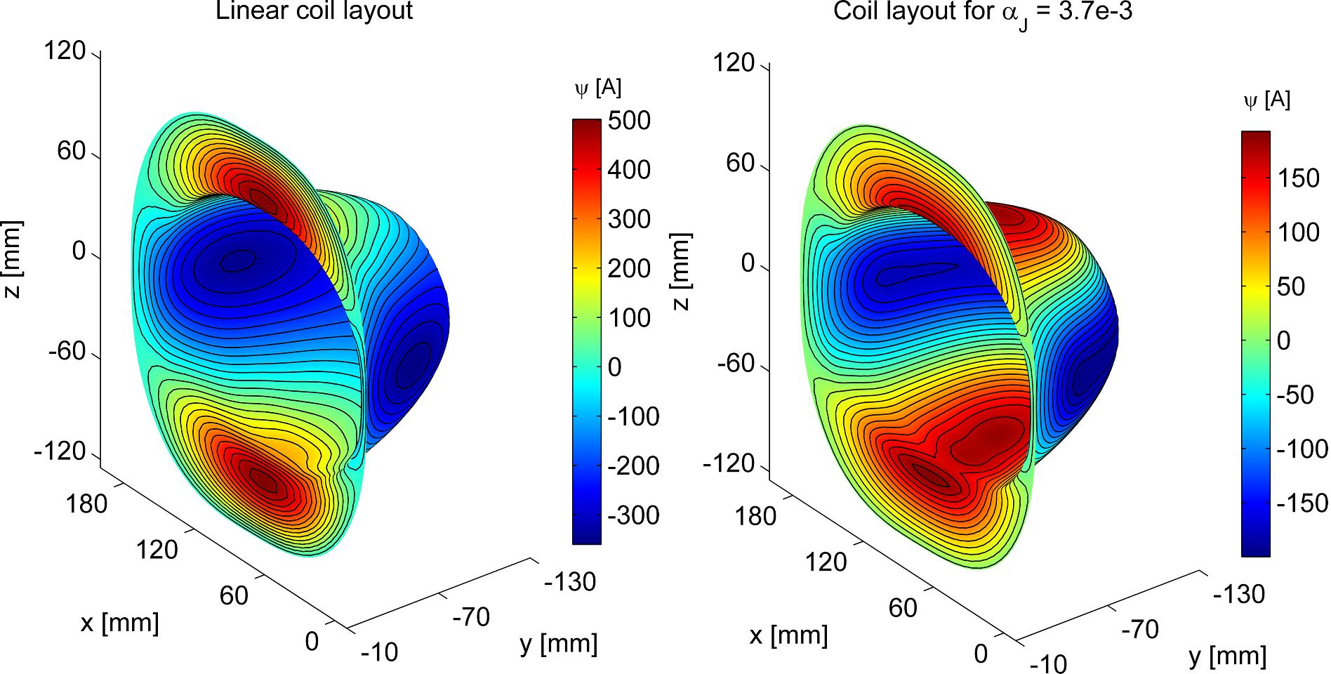
Fig. 5. Wire layouts of the designed linear (left) and nonlinear (right) coils. The nonlinear coil with a larger minimum wire width can afford higher maximum current than the linear one, possibly leading to much higher gradient strength and higher duty cycles.