4245
Eddy Current Characterization of a Multi-Coil Array for Imaging in a Head-Only MR Scanner1Department of Biomedical Engineering, Columbia University in the City of New York, New York, NY, United States, 2Robinson Research Institute, Victoria University of Wellington, Wellington, New Zealand, 3Department of Radiology, Columbia University in the City of New York, New York, NY, United States
Synopsis
As part of a collaborative effort to create a novel compact high-temperature superconductor 1.5 T head-only scanner for improved accessibility of MRI and advanced motor coordination studies, we are developing a 31-coil Multi-Coil (MC) array for linear and non-linear image encoding and concomitant B0 shimming. Here we present a preliminary characterization of the expected eddy currents generated by the unshielded MC array in the unusual scanner assembly at hand based on finite element based electromagnetic simulations.
Introduction
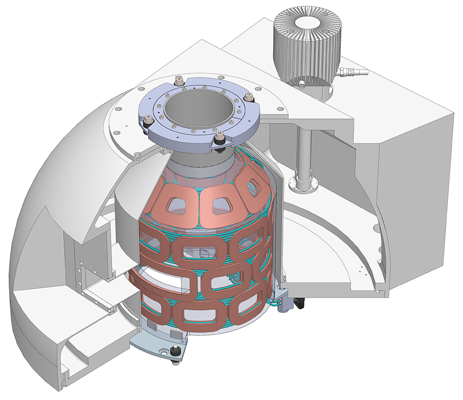
To improve accessibility of magnetic resonance imaging (MRI) and to enable advanced motor coordination studies, we are part of a collaborative effort to develop a compact 1.5 T head-only scanner with the shoulders completely excluded. The compact size of the scanner causes large B0 inhomogeneities1,2 and, therefore, necessitates novel imaging methods which in turn require advanced B0 field modeling capabilities. To this end we developed a Multi-Coil (MC) array capable of generating linear3 and non-linear4 MRI encoding fields and concomitant complex B0 shim fields5. Our solution2 is uniquely suited to the limited space and low power demand of this application (Figure 1).The time-varying encoding fields for MRI create eddy currents (EC) in conductive structures of the scanner, in particular in the magnet thermal shield. ECs create secondary magnetic fields that alter the effective encoding fields and thereby lead to various image artifacts. EC generation is commonly minimized by designing shielded gradient coils and by characterizing the remaining ECs in order to correct for them (so-called preemphasis). By contrast, our MC array is an unshielded coil system. By using a cryogen-free high-temperature superconductor magnet, we eliminated the magnet thermal shield. However, ECs might instead be induced in the copper conduction cooling bus of the magnet. Here we present simulations on the magnitude and temporal behavior of ECs generated in the magnet cooling bus by switching typical linear encoding fields6 along with strategies to minimize them.
Methods
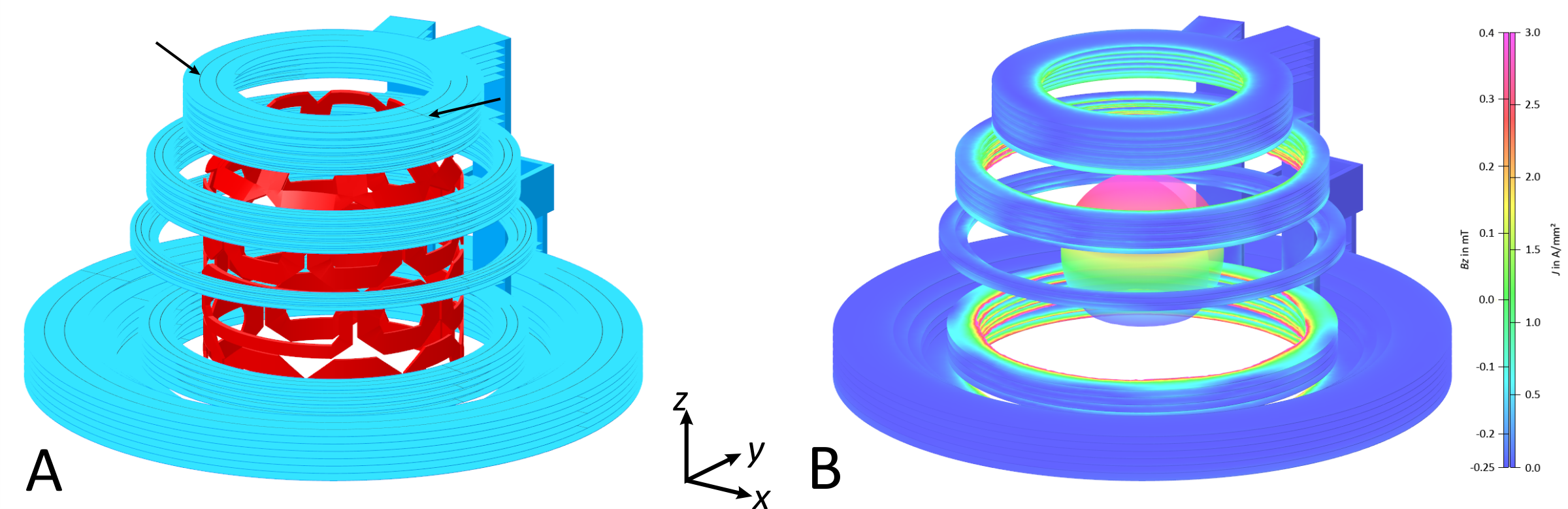
The geometry of the copper bus structure was transferred into a transient electromagnetic FEA model (Figure 2A, Opera, Dassault Systèmes, Vélizy-Villacoublay, France). The copper was modeled with an electrical conductivity of 2 GS/m corresponding to copper at 30 K7. The 31 coil elements of the MC array were added as Biot-Savart conductors (cf. Figure 1). Individual currents needed to generate specific MC fields were simulated using B0DETOX8,9 and applied to the respective conductors in the FEA model. To assess the EC generation, these currents were ramped down linearly from 100% to 0% over 500 µs resembling typical gradient switches, and electromagnetic fields and currents across the cooling bus structure were calculated for various time points after the start of this ramp. At every output time step the z-component of the B0 field was characterized by calculating spherical harmonic (SH) coefficients on a sphere of 100 mm radius around the isocenter (Figure 2B). Two exemplary fields were examined, a Z-gradient of 6 kHz/cm (14.1 mT/m) and an X-gradient of 4 kHz/cm (9.4 mT/m). EC minimization strategies were explored by repeating the EC field simulations for the Z-gradient using a modified bus geometry with radial and circumferential cuts through the copper bus (cf. Figure 2A).Results
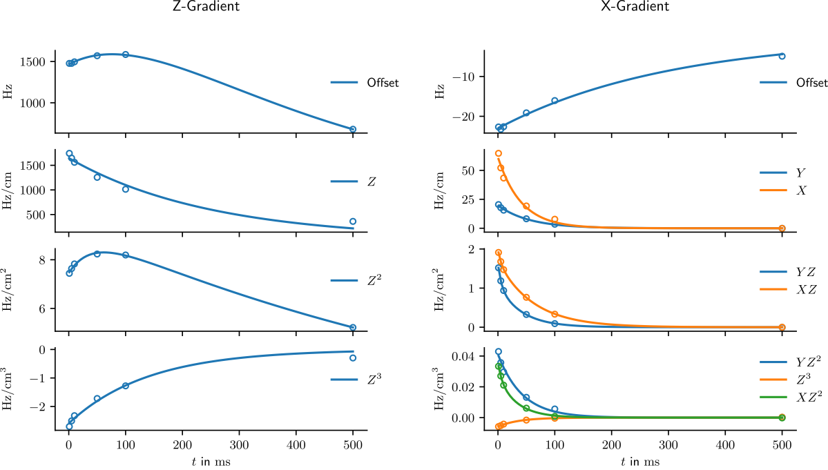
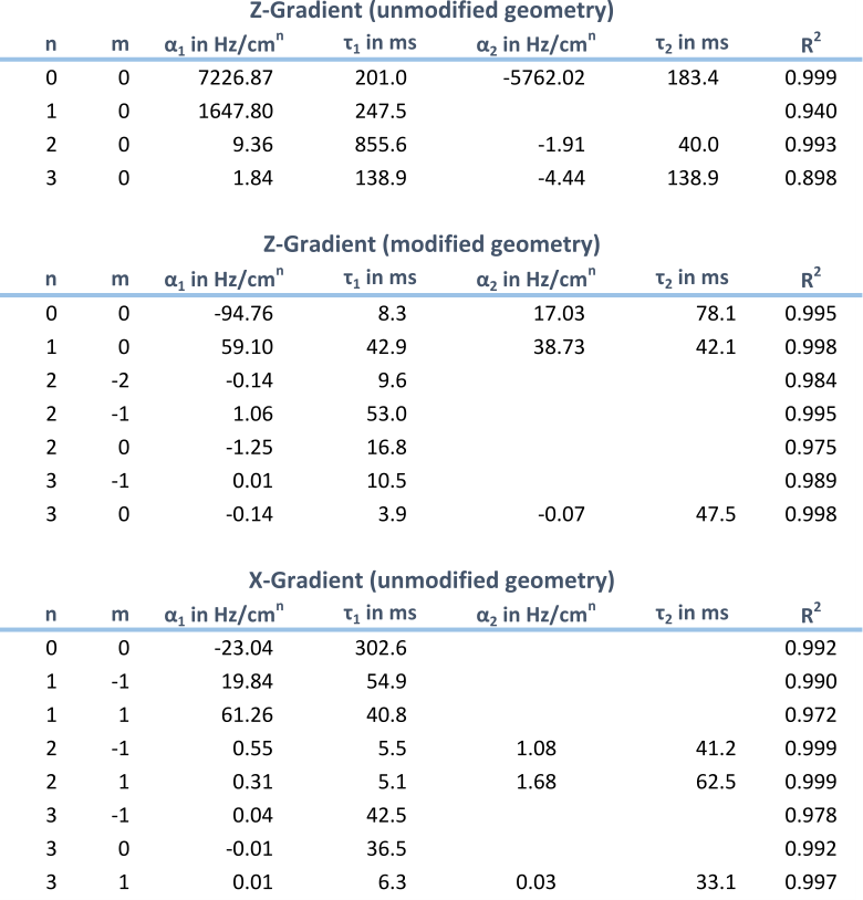
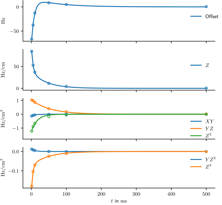
Figure 3 shows the calculated SH coefficients for the unmodified geometry as a function of time. Coefficients that were considered negligible (<5% of the largest EC component) are not shown. The Z-gradient created a significant field offset and Zn terms with the self (Z) term reaching a maximum of 29% of the original gradient strength. The X-gradient created mainly XZn terms with the self (X) term reaching 2% of the original gradient strength. Additionally, this field also created YZn terms with the linear Y term reaching about 30% of the strength of the X term.All SH terms were fitted with exponential functions of the form $$$\sum_n\alpha_ne^{-t/\tau_n}$$$, whereupon n was chosen as 1 or 2 to yield the largest adjusted $$$\bar{R}^2$$$. For the quality of these fits compare Figure 3 and Table 1. The time constants $$$\tau_n$$$ of the self-term ECs of the Z- and X-gradient were 248 ms and 41 ms, respectively, and the remaining time constants were in the same order of magnitude.
EC generation of the Z-gradient in the modified geometry was significantly reduced (Figure 4) with the dominant 0th and 1st order terms <5% of the EC strength in the unmodified case, corresponding to a self-term strength of 1.4% of the gradient strength. The time constants of the corresponding fits were reduced to less than 20% of the corresponding values in the unmodified case (cf. Table 1).
Conclusion & Outlook
The presented simulations revealed that significant eddy currents can be generated in a solid cooling bus structure, leading to spatio-temporal field alterations across the volume of interest and potentially affecting the MRI experiment. ECs can be significantly reduced, however, by employing a slotted design of the otherwise unchanged copper plates of the cooling bus. The copper structure considered in this analysis is expected to be the main source of ECs due to its high conductivity and proximity to the MC array. Other conductive structures such as the RF coil located inside the MC array, or the MC coils themselves have been neglected here, but will need to be included for a comprehensive analysis. Note that all MC channels are actively current compensated which is expected to reduce the latter effect.The ECs observed in this study are larger than values reported in the literature for traditional whole-body systems10. However, the values obtained with the slotted bus design are comparable to conventional MR systems, and it should thus be possible to correct for them using standard methods like preemphasis.
Acknowledgements
This research was supported by the National Institute of Biomedical Imaging & Bioengineering of the National Institutes of Health under award number U01EB025153.References
1. Hunter M, Bouloukakis K, Theilenberg S, Kobayashi N, Juchem C, Parkinson BJ. Passive shimming for a Portable Head-Only scanner. In: Proc. Intl. Soc. Magn. Reson. Med. 27, 1478 (2019).
2. Theilenberg S, Shang Y, Kobayashi N, Parkinson BJ, Juchem C. Multi-Coil Array for Combined Imaging and B0 Shimming in a Portable Head-Only Scanner. In: Proc. Intl. Soc. Magn. Reson. Med. 27, 1480 (2019).
3. Juchem C, Nixon TW, McIntyre S, Rothman DL, de Graaf RA. Magnetic field modeling with a set of individual localized coils. J Magn Reson. 2010;204(2):281-289.
4. Juchem C, Nixon TW, de Graaf RA. Multi-Coil Imaging with Algebraic Reconstruction. In: Proc. Intl. Soc. Magn. Reson. Med. 20, 2545 (2012).
5. Rudrapatna SU, Fluerenbrock F, Nixon TW, de Graaf RA, Juchem C. Combined imaging and shimming with the dynamic multi-coil technique. Magn Reson Med. 2019;81(2):1424-1433.
6. Juchem C, Mullen M, Kumaragamage C, et al. Dynamic Multi-Coil Technique (DYNAMITE) MRI on Human Brain. In: Proc. Intl. Soc. Magn. Reson. Med. 27, 0219 (2019).
7. Ekin J. Experimental Techniques for Low-Temperature Measurements. Oxford University Press; 2006.
8. Juchem C, Herman P, Sanganahalli BG, Brown PB, Mcintyre S, Nixon TW, Green D, Hyder F, de Graaf RA. DYNAmic Multi-coIl TEchnique (DYNAMITE) shimming of the rat brain at 11.7T. NMR Biomed. 2014;27(8):897-906.
9. MR Scientific Engineering for Clinical Excellence (MR SCIENCE) Laboratory software download. http://juchem.bme.columbia.edu/software-and-tools.
10. Papadakis NG, Martin KM, Pickard JD, Hall LD, Carpenter TA, Huang CL-H. Gradient preemphasis calibration in diffusion-weighted echo-planar imaging. Magn Reson Med. 2000;44(4):616-624.
Figures