4242
A Programmable Set of Z-Gradient Array and Active-Shield Array for Magnetic Resonance Imaging
Manouchehr Takrimi1 and Ergin Atalar1,2
1National Magnetic Resonance Research Center, Bilkent University, Ankara, Turkey, 2Department of Electrical and Electronics Engineering, Bilkent University, Ankara, Turkey
1National Magnetic Resonance Research Center, Bilkent University, Ankara, Turkey, 2Department of Electrical and Electronics Engineering, Bilkent University, Ankara, Turkey
Synopsis
A novel programmable set of z-gradient array equipped with an active-shield array is introduced and simulated for diverse applications in magnetic resonance imaging (MRI). The proposed active-shield array can dynamically provide a proper shield for the main array in which its magnetic profile can be programmed based on the required scenario. This is achieved by using a set of independently tunable power amplifiers that feed both array elements individually or in a cluster. As a proof of concept, two sets of arrays are simulated: one for a double-gradient z-coil array and another one possessing a large field of view (FOV).
Purpose
The conventional application-specific gradient and its dedicated active shield sub-system can be replaced by a set of novel programmable array versions. They are highly customizable and offer wide range of new features in addition to conventional functionalities.Method
Gradient array have recently been used for shimming as well as spatial coding and for some cases for both of them1-10 but regarding active-shield array, no general solution has been proposed yet. Gradient active-shield array consists of a series of pre-calculated wire patterns called coil elements. A coil element may be fed individually by a dedicated power amplifier (PA), or a group of elements or clusters can be fed by a common PA in a proper manner. Finding an acceptable configuration for cluster positions under practical constrains leads to nonlinear optimization problems. After positioning the array elements, by calculating the magnetic field created by each element based on analytic or numerical methods and performing appropriate optimizations, a set of suitable feeding waveforms may be computed. The well-known target field method or a combinational scenario of analytical and numerical solutions may be used for better results.Results
A z-gradient coil possessing a large FOV is ideally designed using Maple11 without taking into account the existence of cryostat. The coil consists of 10 pairs of 2x2 mm2 copper rectangular wires of diameter 680 mm and height 1.2 m as shown in Fig. 1. The BZ field plot is shown in Fig. 2 where the contour lines indicate 0.5 $$$\mu$$$T separations. The RMS value for ten feeding currents is 0.501 A leading to 25.4 $$$\mu$$$T/m/Arms efficiency. The FOV diameter (at 0.3% deviation from linearity) is 600 mm. To demonstrate the flexibility of proposed method, a simple array consisting of 10 pairs of uniformly-spaced and independently (but symmetrically) fed wire loops of diameter 786 mm and total height of 1.6 m (look at Fig. 1) is used to design an active-shield array for above mentioned z-gradient coil taking into account 10 mm thick cylindrical aluminum cryostat of diameter 910mm. The stray fields are sampled 1.6 m along the surface of the cryostat to compute necessary feeding currents. To demonstrate the effectiveness of active shielding in the presence of cryostat, trapezoidal currents of 200 $$$\mu$$$s rise, pulse, and fall time with computed amplitudes are fed synchronously to all array elements. Simulation results are shown in Fig. 3 at peak input current for t=400$$$\mu$$$s and before the fall time. The position of cryostat is also shown in the picture. Simulation shows an efficiency of 8.7 $$$\mu$$$T/m/Arms and 7.9% deviation from linearity within the same FOV. As a diverse application, a multi-gradient z-coil array based on similar geometry but new wire positions and feed currents is designed possessing two identical FOVs of diameter 300 mm, symmetrically positioned at ±300 mm on the z-axis. The same uniformly-spaced active-shield array with another set of optimized feeding currents is utilized to perform as a shield. Feeding by a similar trapezoidal current as before, Fig. 4 illustrates the BZ field for overall double FOV z-gradient array and its dedicated shield at t=400$$$\mu$$$s. The contour lines indicate 0.2 $$$\mu$$$T separations. Simulation shows an efficiency of 8.27 $$$\mu$$$T/m/Arms and 10.1% deviation from linearity within both FOVs of 300 mm diameter. It should be note that increasing the number of wires (ten wires in above examples) or clusters greatly improves the overall efficiency of the shield and makes it possible to optimize wide range of other important performance parameters.Discussion
In conventional designs where the main and shield coils are connected in series, wire positions are calculated and optimized to satisfy linearity, efficiency, gradient strength, shielding, and other performance constrains. Also the whole coil is fed by an expensive yet powerful gradient power amplifier capable of delivering high voltages in order to supply enough current for both coils. After construction, only the feeding waveform can be changed to fine tune the performance of whole gradient assembly. In the proposed active-shield array design, the wire positions were set either uniformly or based on system-dependent optimizations and then an optimized set of feeding waveforms (ten in above mentioned design examples) are supplied by less expensive but independent power amplifiers to satisfy the constrains. It is seen that a higher degree of freedom for fine tuning of overall gradient assembly exists in this method. Note that the impedance of individual array elements is much less than the whole coil and hence, higher switching frequencies are also attainable.Conclusion
The benefit of a matched set of z-gradient array and its dedicated active-shield array is four folded: (a) it is highly customizable due to its dynamic nature; (b) it improves the overall imaging speed since the impedance of the individual array elements are considerably less than the main coil and its series connected shield; (c) magnetic field profiling is possible for wide range of MRI applications; (d) if shielding is not concerned, both of the main coil array and its shield array may be used to achieve very high gradient strengths or slew rates. We expect that this realistic simulation study will lead to construction of the gradient system in a near future.Acknowledgements
No acknowledgement found.References
- Wintzheimer S, Driessle T, Ledwig M, et al. A 50-channel matrix gradient system: A feasibility study. Proc. of the ISMRM, Stockholm, Sweden. 2010:3937.
- Juchem C, Rudrapatna SU, Nixon TW, de Graaf RA. Dynamic multi‐coil technique (DYNAMITE) shimming for echo‐planar imaging of the human brain at 7 Tesla. NeuroImage. 2015;105:462–472.
- Juchem C, Green D, de Graaf RA. Multi-coil magnetic field modeling. Journal of Magnetic Resonance. 2013 Nov 1;236:95-104.
- Juchem C, Nixon TW, McIntyre S, et al. Magnetic field modeling with a set of individual localized coils. Journal of Magnetic Resonance. 2010 Jun 1;204(2):281-9.
- Jia F, Littin S, Layton KJ, et al. Design of a shielded coil element of a matrix gradient coil. Journal of Magnetic Resonance. 2017 Aug 1;281:217-28.
- Littin S, Jia F, Layton KJ, et al. Development and implementation of an 84‐channel matrix gradient coil. Magnetic resonance in medicine. 2018 Feb;79(2):1181-91.
- Kroboth S, Layton KJ, Jia F, Littin S, et al. Optimization of coil element configurations for a matrix gradient coil. IEEE transactions on medical imaging. 2017 Aug 23;37(1):284-92.
- Ertan, K. , Taraghinia, S. , Sadeghi, A. and Atalar, E. (2018), A z‐gradient array for simultaneous multi‐slice excitation with a single‐band RF pulse. Magn. Reson. Med, 80: 400-412.
- Ertan, K, Taraghinia, S, Atalar, E. Driving mutually coupled gradient array coils in magnetic resonance imaging. Magn Reson Med. 2019; 82: 1187– 1198.
- Ertan, K., Taraghinia S, Sarıtas EU, Atalar E. Local optimization of diffusion encoding gradients using a z-gradient array for echo time reduction in DWI. In Proceedings of the 26th Annual Meeting of ISMRM, Paris, France, 2018. Abstract# 3194.
- Maple (2018.2). Maplesoft, a division of Waterloo Maple Inc., Waterloo, Ontario.
Figures
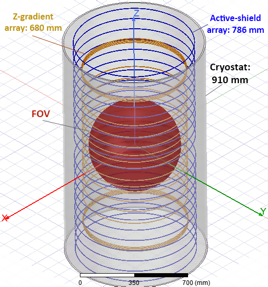
Figure 1: The geometry of proposed
z-gradient array, active-shield array, and the cryostat. Z-gradient array
consists of 10
pairs of 2x2 mm2 copper rectangular wires of diameter 680 mm and
height 1.2 m. Active-shield array consists
of 10 pairs of same copper wires of diameter 786 mm and height 1.6 m. The cryostat is also shown as 10 mm thick
cylindrical aluminum of height 1.6 m.
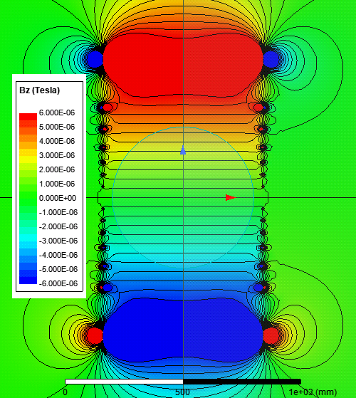
Figure 2: BZ field plot of an
ideal large FOV z-gradient coil of 1.2 m height consisting of 10 pairs of 2x2 mm2
rectangular cross section of circular wires of diameter 680 mm where the coil
axis coincides with the z-axis. The contour lines indicate 0.5 $$$\mu$$$T separations. The RMS value for feeding currents is 0.5 A leading to 25.4 $$$\mu$$$T/m/Arms efficiency. The FOV diameter
(at 0.3% deviation from linearity) is 600 mm which is 88% of the coil diameter.
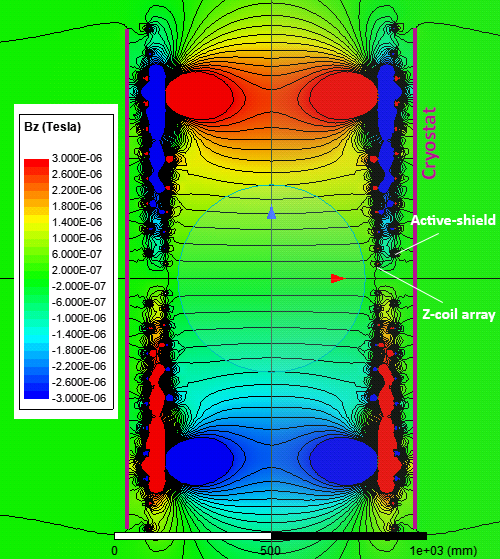
Figure 3: BZ field plot of the
same z-gradient coil shown in Fig. 2 which is shielded by an active-shield
array consisting
of 10 pairs of uniformly-spaced and independently fed wire
loops of diameter 786 mm and total height of 1.6 m. The RMS of all feeding
currents (both of the main coil and its shield) is 0.46 A. An
efficiency of 8.7 $$$\mu$$$T/m/Arms and 7.9% deviation from
linearity can be seen within the same FOV diameter. A 10 mm thick cylindrical aluminum cryostat of
diameter 910 mm is shown by thick vertical purple lines at both sides.
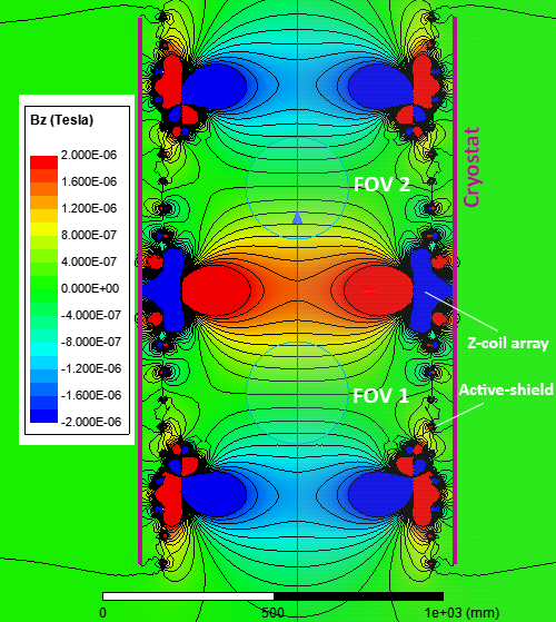
Figure 4: BZ field plot of double-gradient z-gradient array along with its dedicated active-shield array
fed by a set of trapezoidal currents of proper amplitudes. The main z-gradient
array consists of 10 pairs of the same copper wires of diameter 680 mm and
height 1.2 m where the coil axis coincides with the z-axis. The shield configuration is exactly the same
shown in Fig. 2 except with new optimized currents. The RMS of all feeding currents is 0.62 A. An efficiency of 8.27 $$$\mu$$$T/m/Arms and 10.1% deviation from linearity is seen within both
FOVs. Both FOV diameters are 300 mm.