4241
Gradient coil design and optimization with equivalent magnetic dipole method for ultra-low field MRI systems
Sheng Shen1,2, Zheng Xu1, Neha Koonjoo2,3,4, and Matthew S. Rosen2,3,4
1Chongqing University, Chongqing, China, 2MGH/A.A. Martinos Center for Biomedical Imaging, Cambridge, MA, United States, 3Department of Physics, Harvard University, Cambridge, MA, United States, 4Harvard Medical School, Boston, MA, United States
1Chongqing University, Chongqing, China, 2MGH/A.A. Martinos Center for Biomedical Imaging, Cambridge, MA, United States, 3Department of Physics, Harvard University, Cambridge, MA, United States, 4Harvard Medical School, Boston, MA, United States
Synopsis
The gradient subsystem is an essential part of an MRI system. Figures of merit for these systems include slew rate and the gradient field linearity. Our previously described 6.5 mT ultra-low-field MRI scanner has marginal gradient performance with low slew rates (minimal rise time of 750µs) and low efficiency (around 10µT/m/A). We describe here the optimization of a new gradient coil system with improved slew rate and efficiency. We introduce the equivalent magnetic dipole method to design biplanar gradient coils, and our design study of the geometric parameters of the gradient coil (including the coil pattern, its size and density).
Introduction
The gradient subsystem is an essential part of an MRI system. Figures of merit for these systems include slew rate as well as the gradient field linearity. Our previously described 6.5 mT (276 kHz) ultra-low-field (ULF) MRI scanner [1] has marginal gradient performance with low slew rates (minimal rise time of 750µs) and low efficiency (around 10µT/m/A). We describe here the optimization of a new gradient coil system with improved slew rate and efficiency. We introduce here the equivalent magnetic dipole method (EMDM) [2] to design biplanar gradient coils, and our design study of the geometric parameters of the gradient coil (including the coil pattern, its size and density).Method
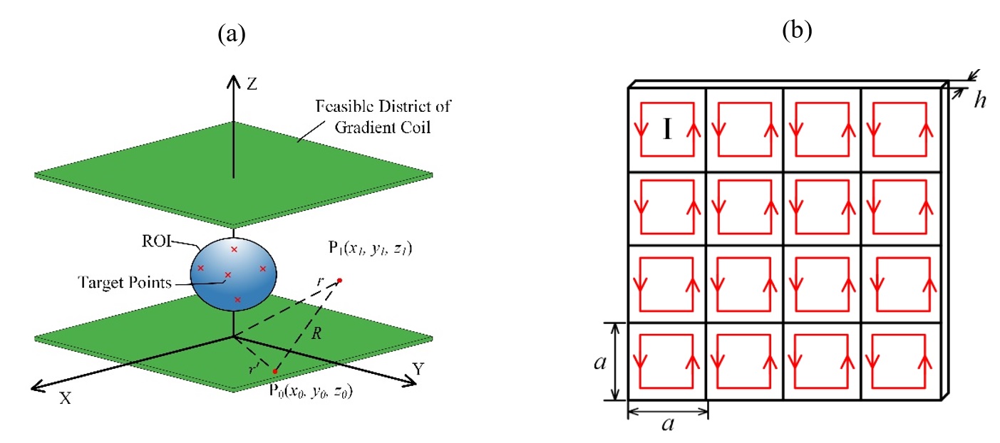
he biplanar gradient set can be described as the sketch shown in figure 1(a). The green planes represent the allowable locations for wire placement and the blue spherical region is region of interest (ROI). In EMDM, the gradient coil was approximated by a magnetic dipole matrix. The gradient coil design problem was converted to obtaining an optimal magnetic dipole matrix which can generate required gradient magnetic field. The rectangle current loop in figure 1(b) was approximately regarded as magnetic dipole; then, the magnetic field distribution in ROI generated by the magnetic dipole was calculated as in equation (1).$$\vec{B}=\frac{\mu_{0}}{4\pi}(\vec{m}\cdot\triangledown)\triangledown\frac{1}{r}$$(1)
However, we cannot directly solve this equation (1), because gradient coil design problem is a typical ill-posed inverse problem. It is usually solved by applying a regularization method, which converts this ill-posed inverse problem into a minimization problem. The minimization problem is described in equation (2)
$$Min: F=\frac{1}{n}\sum_i^n(B_{z,i}-B_{target,i})^{2}+\lambda PE$$(2)
where,Bz is the magnetic field generated by magnetic dipole, Btarget is the ideal gradient magnetic field, PE is the magnetic energy of magnetic dipole. is the coefficient of regularization term. The solution of equation (2) is the magnetic dipole distribution. We then demonstrated that the magnetic dipole distribution was the stream function of equivalent magnetization current of magnetic dipole, which was then converted to coil pattern with “stream function method” [3].
Results
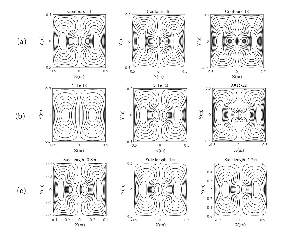
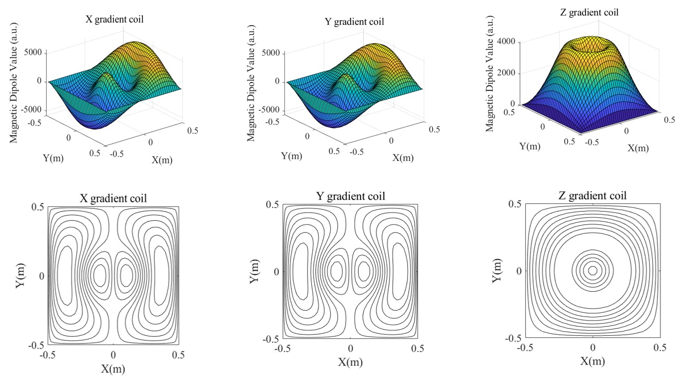
Using the EMDM approach, we implemented gradient-coil design and studied the realization parameters by analyzing gradient-coil performance with FEM (finite element method) simulation. Figure 2 presents the gradient coil in different densities, different coil patterns, different sizes which were obtained with different regularization parameters. All these gradient coils were analyzed in FEM software, from which we acquired the inductance, efficiency and linearity of each gradient coil; and that were used to reveal the relationship between the geometric parameters and gradient coil performance. Based on the study of geometric parameters, we designed a new gradient system for our ULF system, with the magnetic dipole distribution and corresponding coil shown in figure 3. We have also built a 1/3-scale model of the X gradient to verify the design. Figure 4 (a) shows the prototype and figure 4 (b) shows the magnetic field maps where one is obtained by simulation in FEM software, the other one is measurement with gaussmeter (Bell, 8030) respectively.Discussion and Summary
Here, we introduced EMDM and developed it by proposing a new regularization term. Since the optimization method for gradient coil design method has been well developed, we focused on the geometric parameters of gradient coil. The study on geometric parameters revealed the influence of the elements of gradient coil performance, which could eventually be exploited in gradient coil optimization.Acknowledgements
This work was supported by fundings from the National Natural Science Foundation of China (No. 51677008 and 51707028) and the Fundamental Research Funds for the Central Universities (No.2018CDJDDQ0017).References
[1] M. Sarracanie, C. D. LaPierre, N. Salameh, D. E. J. Waddington, T. Witzel, and M. S. Rosen, “Low-Cost High-Performance MRI,” Sci Rep, vol. 5, no. 1, p. 15177, Oct. 2015. [2] Zheng, X. Equivalent magnetic dipole method used to design gradient coil for unilateral magnetic resonance imaging. Chin. Phys. B Vol. 27, No. 5 (2018) 058702 [3] Turner R. A target field approach to optimal coil design. J Phys D Appl Phys 1986; 19: L147.Figures
Figure
1. Sketch of mathematic model.(1)Biplanar gradient coil sketch (2)Equivalent
magnetic dipole matrix of gradient coil.
Figure
2. Design results with EMDM. (a) Gradient coil in different coil density which
is converted from the same magnetic matrix; (b) Gradient coil in different coil
pattern which is obtained by adjusting regularization term coefficient; (c)
Gradient coil in different size.
Figure
3. Design result of the gradient coil set for ULF MRI system. The top panel
describes the magnetic dipole distribution, and the bottom panel is the corresponding
gradient coil pattern.
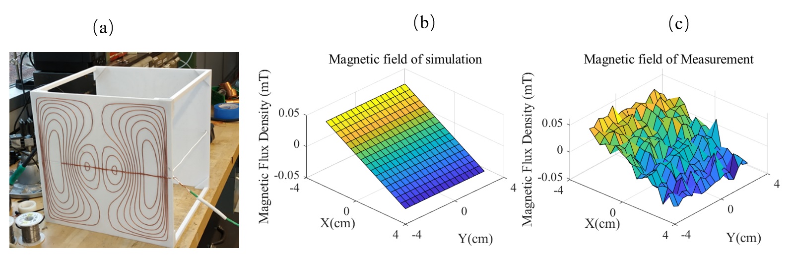
Figure 4.
Prototype design. (a) scale-down model of X gradient coil; (b) magnetic field
distribution on the middle plane of ROI (same as in Figure1) obtained by FEM
simulation; (c) magnetic field distribution on the middle plane of ROI measured
by gaussmeter.